Fuel injection valve

a fuel injection valve and fuel technology, applied in the direction of fuel injection apparatus, combustion engine, charge feed system, etc., can solve the problem that the prior art fuel injection valve is insufficient to meet these regulations

Active Publication Date: 2006-06-27
TOYOTA JIDOSHA KK +2
View PDF18 Cites 36 Cited by
  • Summary
  • Abstract
  • Description
  • Claims
  • Application Information

AI Technical Summary

Benefits of technology

[0008]It is a task of the present invention to provide a fuel injection valve capable of atomizing fuel excellently.

Problems solved by technology

Accordingly, there is a possibility that the above fuel injection valve of the prior art will be insufficient to fulfil these regulations.

Method used


Image

  • Fuel injection valve
  • Fuel injection valve
  • Fuel injection valve

Examples


Embodiment Construction

[0056]Referring to the accompanying drawings, each embodiment of the present invention will be explained below.

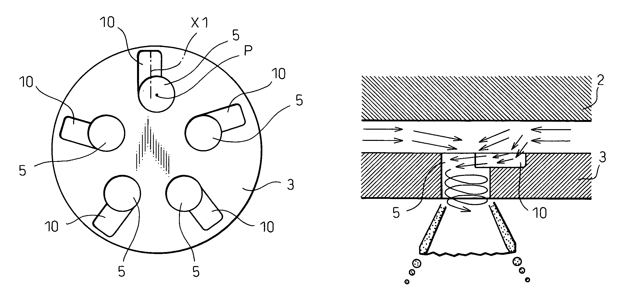
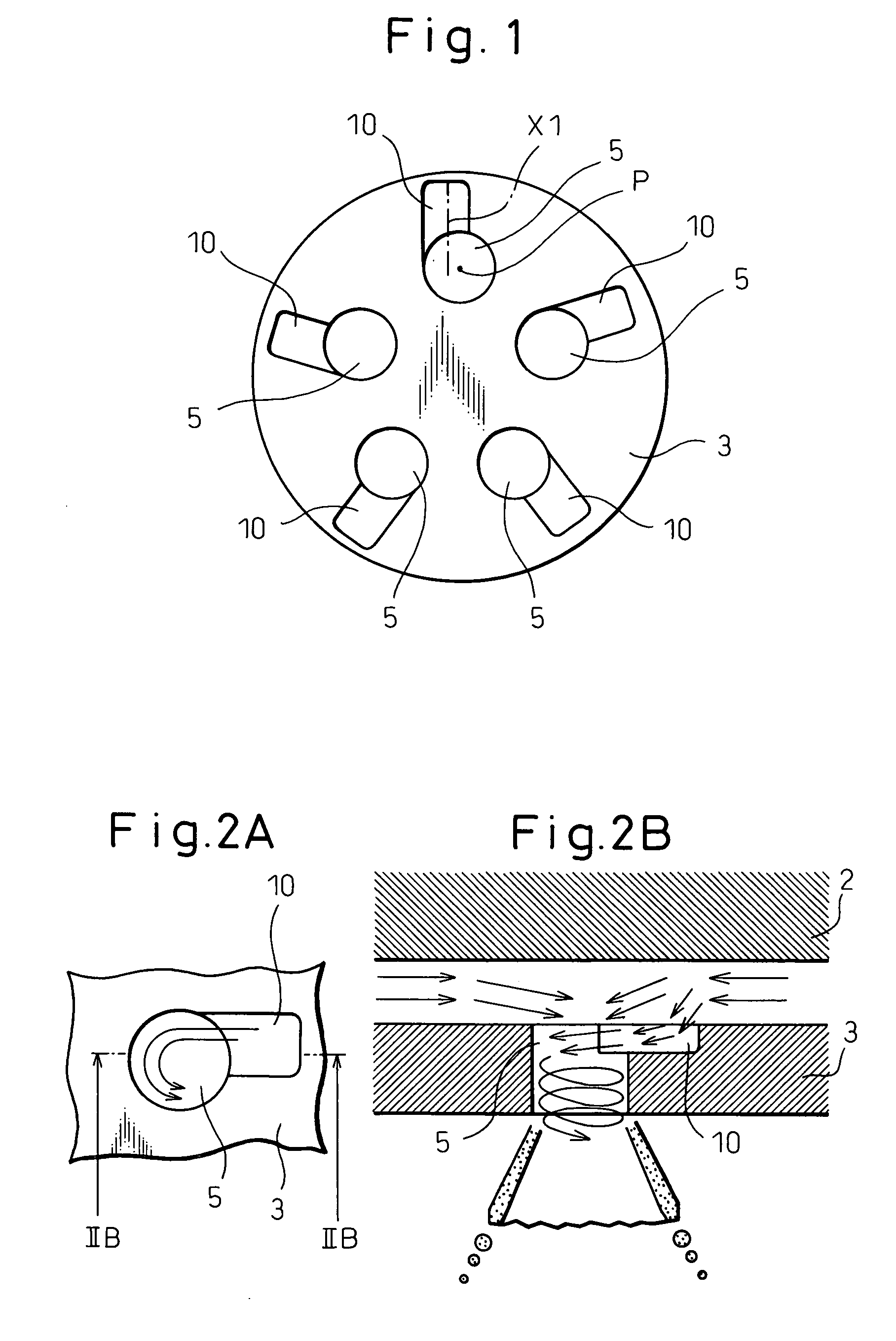
[0057]First of all, the first embodiment is explained as follows. FIG. 1 is a top view of the metering plate 3 provided in the first embodiment, that is, FIG. 1 is a view of the metering plate 3, wherein the view is taken from the upstream side of a flow of fuel. A plurality of nozzle holes 5 (in this case, five nozzle holes) are provided on the metering plate 3. On an upper face of the metering plate 3, the vortex flow generator grooves 10 are provided.

[0058]As shown in the drawing, each vortex flow generator groove 10 is formed as follows. Center line X of the vortex flow generator groove 10 in the longitudinal direction is substantially directed from the circumferential side of the metering plate 3 to the center. However, center line X of the vortex flow generator groove 10 in the longitudinal direction is shifted from center P of the nozzle hole 5 so that center line X ...


PUM


Abstract

There is provided a fuel injection valve in which nozzle holes are formed on a metering plate and fuel flowing on a face of the metering plate on the upstream side is injected outside of a face of the metering plate on the downstream side through the nozzle holes. The fuel injection valve includes a vortex flow generator means for changing a flow of fuel passing in each nozzle hole into a vortex flow, wherein the vortex flow generator means is provided on the upstream side of the metering plate. The vortex flow means is a vortex flow generator groove provided on an upper face of the metering plate and connected with a wall face of an entrance of the nozzle hole, and a main stream of fuel flowing in the groove is directed to a position shifted from the center of the nozzle hole. Alternatively, the vortex flow means is a protrusion formed on an upper face of the metering plate. A flow of fuel is changed into a vortex flow in the nozzle hole and injected from the nozzle hole. Therefore, fuel can be excellently atomized and diffused as a megaphone-shape without being formed into a liquid column spray.

Description

BACKGROUND OF THE INVENTION[0001]1. Field of the Invention[0002]The present invention relates to a fuel injection valve.[0003]2. Description of the Related Art[0004]In order to inject fuel into a cylinder of an internal combustion engine, a fuel injection valve is used. The following type of fuel injection valve is provided. As shown in FIG. 12, the metering plate 3 is arranged in the front of the forward end portion of the needle 2 which is slidably provided in the valve body 1. Via the fuel passage 4 formed between the valve body 1 and the needle 2, fuel flowing between the lower face of the needle 2 and the upper face of the metering plate 3 is injected from the nozzle hole 5 formed on the metering plate 3. FIG. 13 is a top view of the metering plate 3, on which a plurality of nozzle holes 5 are equally formed. FIG. 14A is a top view showing a flow of fuel around one nozzle hole 5. FIG. 14B is a sectional side view of the flow of fuel around the nozzle hole 5. In this case, fuel ...

Claims


Application Information

Patent Timeline
Patent Type & Authority Patents(United States)
IPC IPC(8): B05B1/26F02M61/00F02M61/18F02B5/00F02M61/16
CPCF02M61/162F02M61/1833F02M61/1846F02M61/1853
Inventor SUGIMOTO, TOMOJIROTAKEDA, KEISOFURUNO, SHIGEOSAITO, KIMITAKATANI, YASUHIDEOKAMOTO, ATSUYAKATO, TAKEHIKONAKASHIMA, TATSUSHI
Owner TOYOTA JIDOSHA KK
Why Eureka
Try Eureka