Method and apparatus to decrease combustor emissions

a combustor and emission reduction technology, applied in the field of combustor, can solve the problems of poor mixing and hot spots, high co/hc emissions, and difficulty in simultaneous control of low power co/hc and smoke emission, and achieve the effect of facilitating the reduction of an amount of emissions from a combustor

Inactive Publication Date: 2005-03-15
GENERAL ELECTRIC CO
View PDF12 Cites 104 Cited by
  • Summary
  • Abstract
  • Description
  • Claims
  • Application Information

AI Technical Summary

Benefits of technology

In one aspect, a method for operating a gas turbine engine to facilitate reducing an amount of emissions from a combustor is provided. The combustor includes a mixer assembly including a pilot mixer, a main mixer, and a centerbody that extends therebetween. The pilot mixer includes a pilot fuel nozzle and a plurality of axial swirlers. The main mixer includes a main swirler and a plurality of fuel injection ports. The method comprises injecting fuel into the combustor through the pilot mixer, such that the fuel is discharged downstream from the pilot mixer axial swirlers, and directing flow exiting the pilot mixer with a lip extending from the centerbody into a pilot flame zone downstream from said pilot mixer.

Problems solved by technology

Poor mixing and hot spots can occur both at the dome, where the injected fuel must vaporize and mix prior to burning, and in the vicinity of the dilution holes, where air is added to the rich dome mixture.
However, the simultaneous control of low power CO / HC and smoke emission is difficult with such designs because increasing the fuel / air mixing often results in high CO / HC emissions.
This may result in a long jet flames characteristic of a low swirl number flow.
Such pilot flames produce high smoke, carbon monoxide, and hydrocarbon emissions and have poor stability.
Continued operation with such fuel impingement may cause deposit formation, or may permit the fuel to become entrained within the main mixer flow.
Both of these adverse effects may facilitate a reduced average fuel residence within the flame zone, resulting in an even smaller and cooler flame zone, and reduced low power combustion efficiency.

Method used


Image

  • Method and apparatus to decrease combustor emissions
  • Method and apparatus to decrease combustor emissions
  • Method and apparatus to decrease combustor emissions

Examples


Embodiment Construction

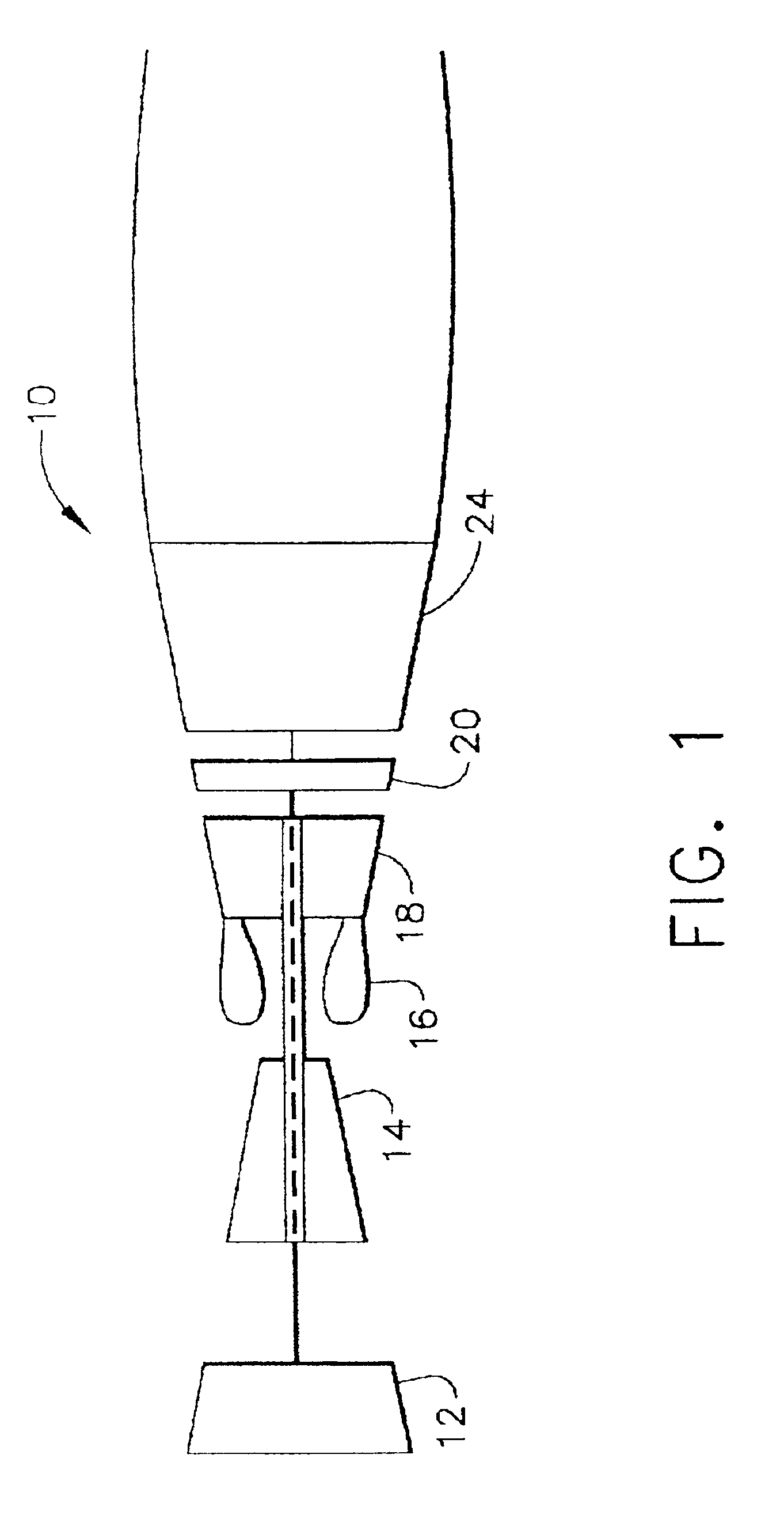
FIG. 1 is a schematic illustration of a gas turbine engine 10 including a low pressure compressor 12, a high pressure compressor 14, and a combustor 16. Engine 10 also includes a high pressure turbine 18 and a low pressure turbine 20.

In operation, air flows through low pressure compressor 12 and compressed air is supplied from low pressure compressor 12 to high pressure compressor 14. The highly compressed air is delivered to combustor 16. Airflow (not shown in FIG. 1) from combustor 16 drives turbines 18 and 20.

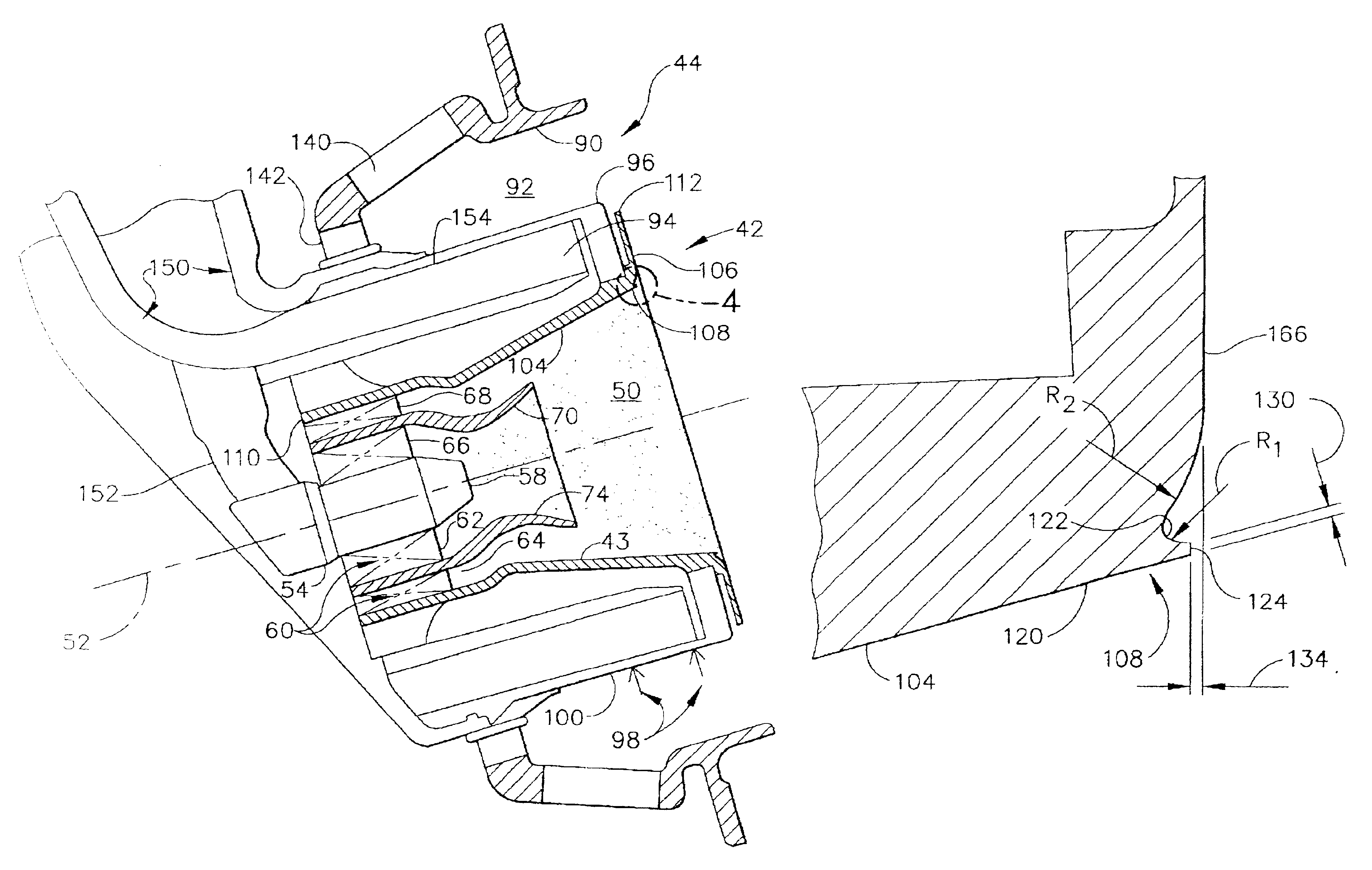
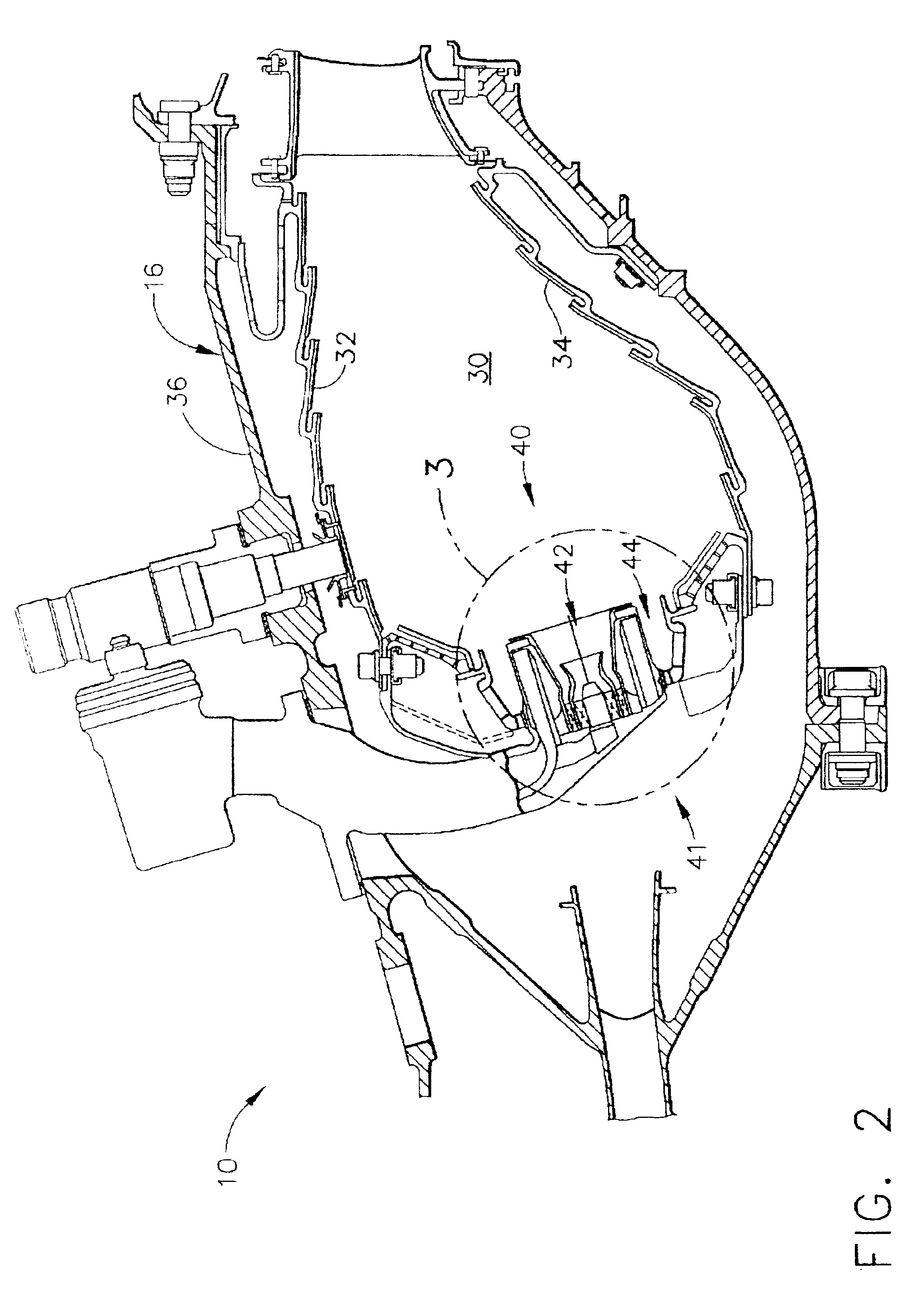
FIG. 2 is a cross-sectional view of combustor 16 for use with a gas turbine engine, similar to engine 10 shown in FIG. 1, and FIG. 3 is an enlarged view of combustor 16 taken along area 3. FIG. 4 is an enlarged view of the combustor shown in FIG. 3 taken along area 4. In one embodiment, the gas turbine engine is a CFM engine available from CFM International. In another embodiment, the gas turbine engine is a GE90 engine available from General Electric Company, Cincinnati, Oh...


PUM


Abstract

A method for operating a gas turbine engine facilitates reducing an amount of emissions from a combustor. The combustor includes a mixer assembly including a pilot mixer, a main mixer, and a centerbody that extends therebetween. The pilot mixer includes a pilot fuel nozzle and a plurality of axial swirlers. The main mixer includes a main swirler and a plurality of fuel injection ports. The method comprises injecting fuel into the combustor through the pilot mixer, such that the fuel is discharged downstream from the pilot mixer axial swirlers, and directing flow exiting the pilot mixer with a lip extending from the centerbody into a pilot flame zone downstream from said pilot mixer.

Description

BACKGROUND OF THE INVENTIONThis application relates generally to combustors and, more particularly, to gas turbine combustors.Air pollution concerns worldwide have led to stricter emissions standards both domestically and internationally. Aircraft are governed by both Environmental Protection Agency (EPA) and International Civil Aviation Organization (ICAO) standards. These standards regulate the emission of oxides of nitrogen (NOx), unburned hydrocarbons (HC), and carbon monoxide (CO) from aircraft in the vicinity of airports, where they contribute to urban photochemical smog problems. In general, engine emissions fall into two classes: those formed because of high flame temperatures (NOx), and those formed because of low flame temperatures which do not allow the fuel-air reaction to proceed to completion (HC & CO).At least some known gas turbine combustors include between 10 and 30 mixers, which mix high velocity air with a fine fuel spray. These mixers usually consist of a single...

Claims


Application Information

Patent Timeline
Patent Type & Authority Patents(United States)
IPC IPC(8): F23R3/02F23R3/28F23R3/16F23R3/14
CPCF23R3/286F23R3/16F23D2900/00016
Inventor MANCINI, ALFRED A.VERMEERSCH, MICHAEL L.THOMSEN, DUANE D.DANIS, ALLEN M.COOPER, JAMES N.LOHMUELLER, STEVEN J.MONGIA, HUKAM C.
Owner GENERAL ELECTRIC CO
Why Eureka
Try Eureka