Metamaterial

a technology of metals and materials, applied in the field of metals, can solve the problems of less desirable active control of the masses m/sub>r/sub>, high levels of attenuation in the transmission characteristics of materials at these frequencies, and achieve the effect of enhancing the attenuation of acoustic transmission

Active Publication Date: 2016-01-21
BAE SYSTEMS PLC
View PDF3 Cites 41 Cited by
  • Summary
  • Abstract
  • Description
  • Claims
  • Application Information

AI Technical Summary

Benefits of technology

[0025]It may be that the resonator in a layer is coupled to the resonator of an neighbouring layer, for example via the at least one active element. It may be that the resonator in a layer is coupled to both resonators in both neighbouring layers. It may be that the resonators in all layers are coupled to the resonators of both of their neighbouring layers or, in the case of layers at the ends of the metamaterial, to the resonator of their neighbouring layer. It may be that the active element is configured to enhance the attenuation of acoustic transmission by control of reactive forces between resonator elements.
[0027]It may be that the active element is configured to enhance the attenuation of acoustic transmission according to optimisation algorithm. It may be that the optimisation algorithm minimises the movement of an element of a layer at a first end of the layers in response to movement of an element of a layer at a second, opposite, end of the layers. The optimisation algorithm may be an optimal feedforward algorithm, for example a Filtered-x Least-Mean-Square (FxLMS) algorithm. The optimisation algorithm may be an optimal feedback algorithm, for example a H-infinity algorithm.

Problems solved by technology

Subsequent to the development of metamaterials exhibiting such (full or partial) photonic bandgaps, attempts were made to develop metamaterials exhibiting phononic bandgaps, i.e. regions in the frequency spectrum in which the transmissivity of sound quanta or phonons is greatly reduced, leading to very high levels of attenuation.
This leads to high levels of attenuation in the transmission characteristics of the material at these frequencies.
However, active control of the masses mr is less desirable than passive control, as it is more complex.

Method used


Image

  • Metamaterial
  • Metamaterial
  • Metamaterial

Examples


Embodiment Construction

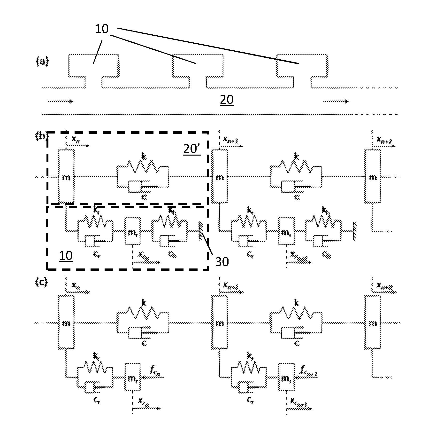
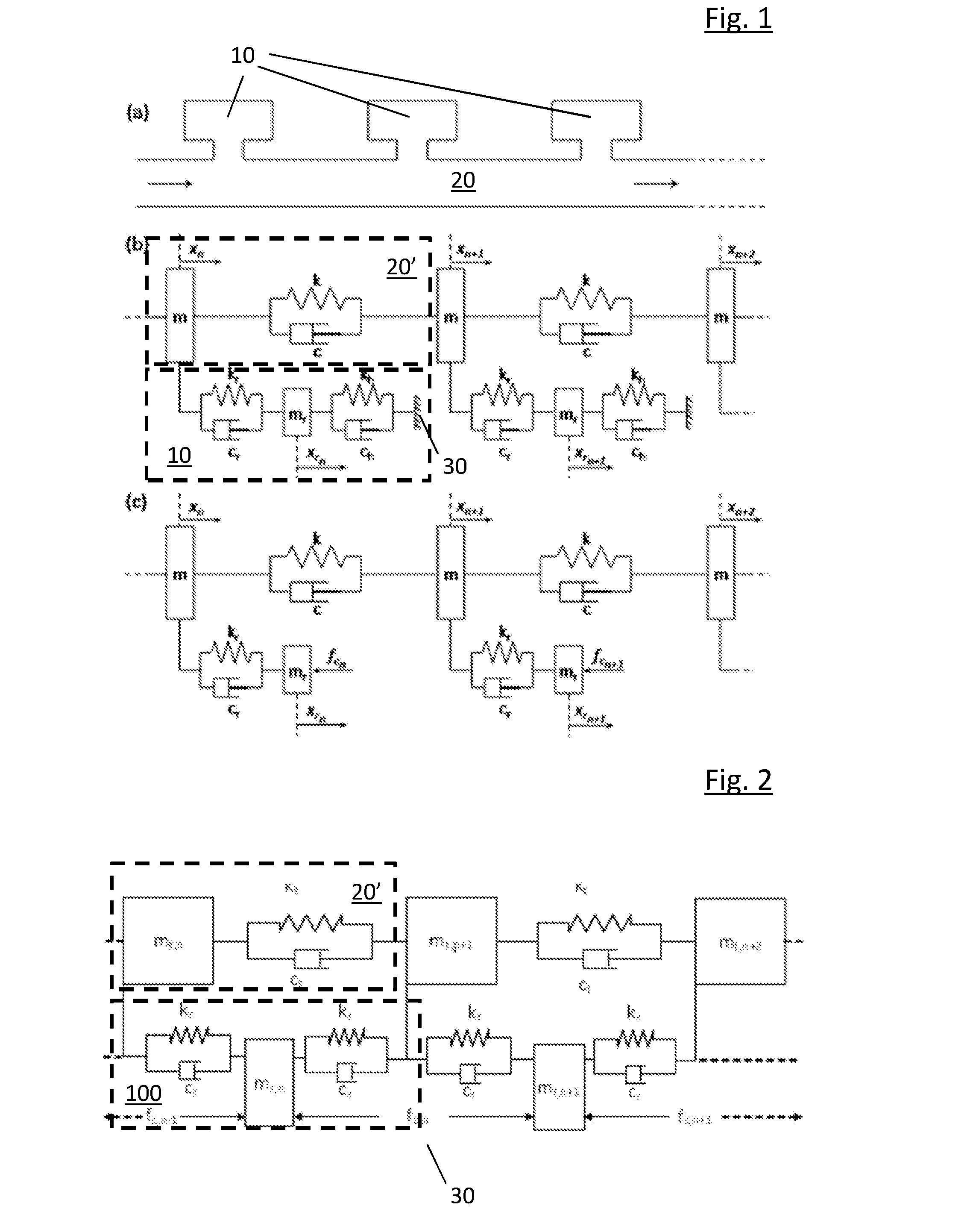
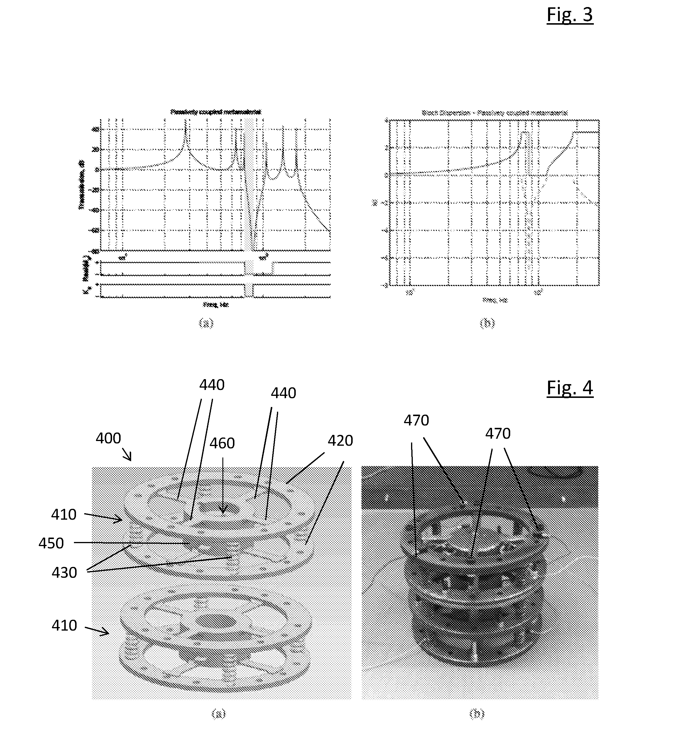
[0037]An example embodiment of the invention was manufactured in the form of an active 1-dimensional viscoelastic metamaterial consisting of a chain of transmission masses connected to each other and to resonator masses via spring elements. This locally resonant, periodic metamaterial has been developed as a proof-of-concept for a vibration isolator providing good attenuation at low frequencies. The example material achieves DNG behaviour through passive coupling of resonators to two transmission masses; in contrast, prior-art materials have one resonator mass per transmission mass and require active control to achieve double negativity.

[0038]The passively occurring band gap is enhanced using an active control architecture. Since locally resonant designs produce materials with dispersive properties, the beneficial DNG behaviour and low-frequency bandgap, although achieved passively, is in this example limited to fixed and narrow frequency bands. Active control was therefore employed...


PUM

PropertyMeasurementUnit
acoustic transmissionaaaaaaaaaa
transmission structureaaaaaaaaaa
transmission structuresaaaaaaaaaa

Abstract

A metamaterial (400) for attenuating acoustic transmission comprises a plurality of layers (410). Each layer (410) comprises a transmission structure (420) and a resonator (450), coupled to the transmission structure (420). The transmission structure (420) in a layer (410) is coupled to the transmission structures (420) of the layers (410) neighbouring said layer (410). The resonator (450) in a layer (410) is coupled to the transmission structure (420) of the layers (410) neighbouring said layer (410).

Description

FIELD OF THE INVENTION[0001]This invention relates to the field of metamaterials. In particular, the invention relates to an artificial material engineered to have a low transmissivity of sound waves over a range of acoustic frequencies.BACKGROUND TO THE INVENTION[0002]Metamaterials are artificial materials that are constructed to have particular properties, typically properties that are not readily found in natural materials. An example of metamaterials is microstructured optical materials constructed to have a very low transmissivity of light over a range of electromagnetic frequencies. Those frequencies are typically referred to as a photonic bandgap, in analogy to the bandgaps seen in the behaviour of electrons in semiconductors. At least some photonic bandgaps can be understood in terms of Bragg scattering of photons in periodic microstructured material. The term “bandgap” is often used to describe a low transmissivity resulting from the structure of the metamaterials, even whe...

Claims


Application Information

Patent Timeline
Patent Type & Authority Applications(United States)
IPC IPC(8): G10K11/172B23K26/00B23K26/342
CPCG10K11/172B23K26/342B33Y80/00B23K2203/14B33Y10/00B23K26/0006G10K11/04G10K2210/3026G10K2210/3027G10K2210/32271B23K2103/14
Inventor DALEY, STEPHENREYNOLDS, MATTHEW JOHN
Owner BAE SYSTEMS PLC
Why Eureka
Try Eureka