Flexible shower arm assembly

a shower arm and flexible technology, applied in the direction of adjustable joints, screw threaded joints, mechanical instruments, etc., can solve the problems of leakage at the joints, looseness, and failure to hold the desired position

Inactive Publication Date: 2006-06-27
WATER PIK INC
View PDF309 Cites 62 Cited by
  • Summary
  • Abstract
  • Description
  • Claims
  • Application Information

AI Technical Summary

Benefits of technology

[0014]Accordingly, it is an object of the present invention to provide a flexible shower arm that can be repeatably adjusted to a variety of positions to allow control of the direction of spray from a shower head.

Problems solved by technology

This type of rigid link structure often leaks at the joints and can become loose and fail to hold the desired position.

Method used


Image

  • Flexible shower arm assembly
  • Flexible shower arm assembly
  • Flexible shower arm assembly

Examples


Embodiment Construction

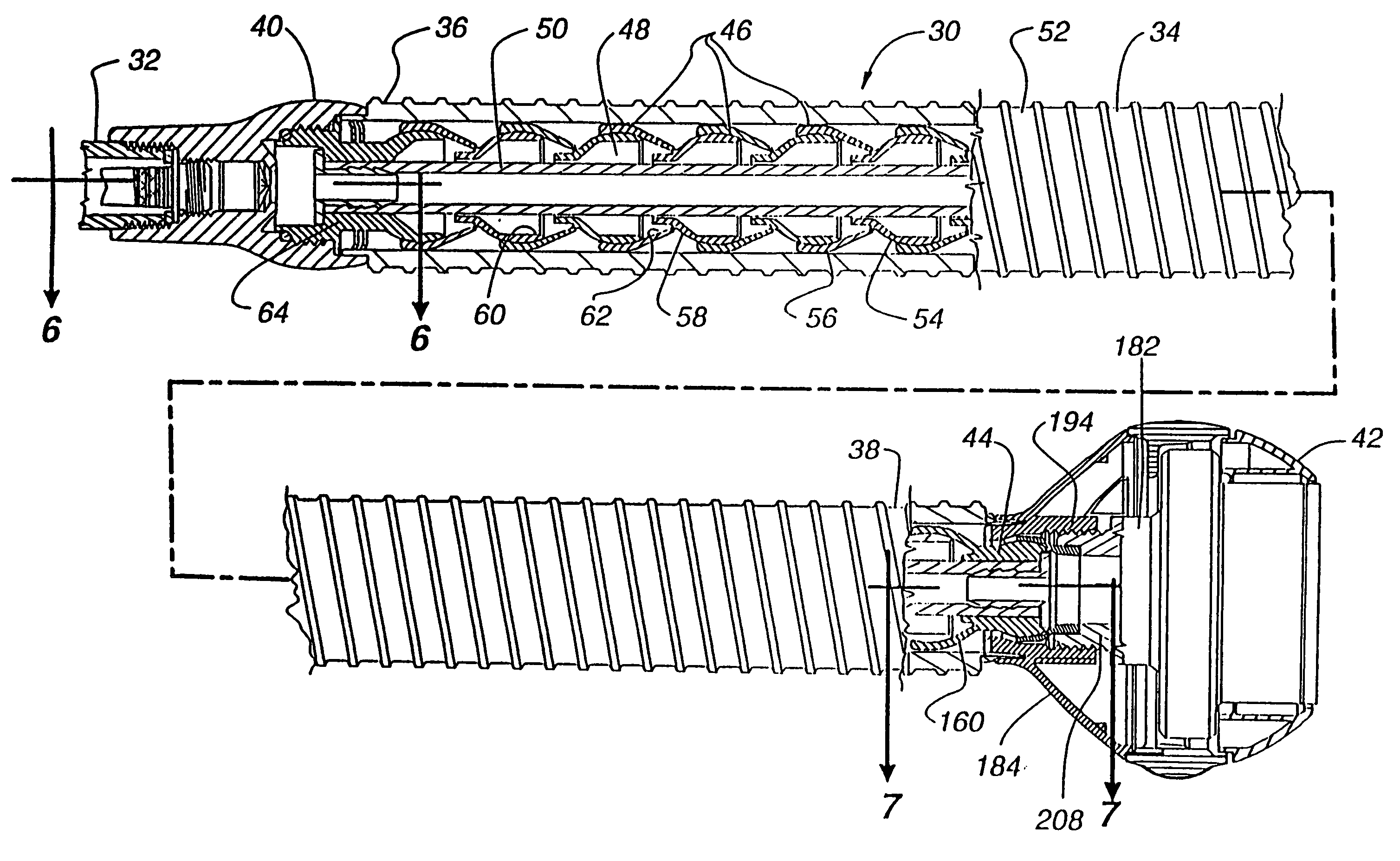
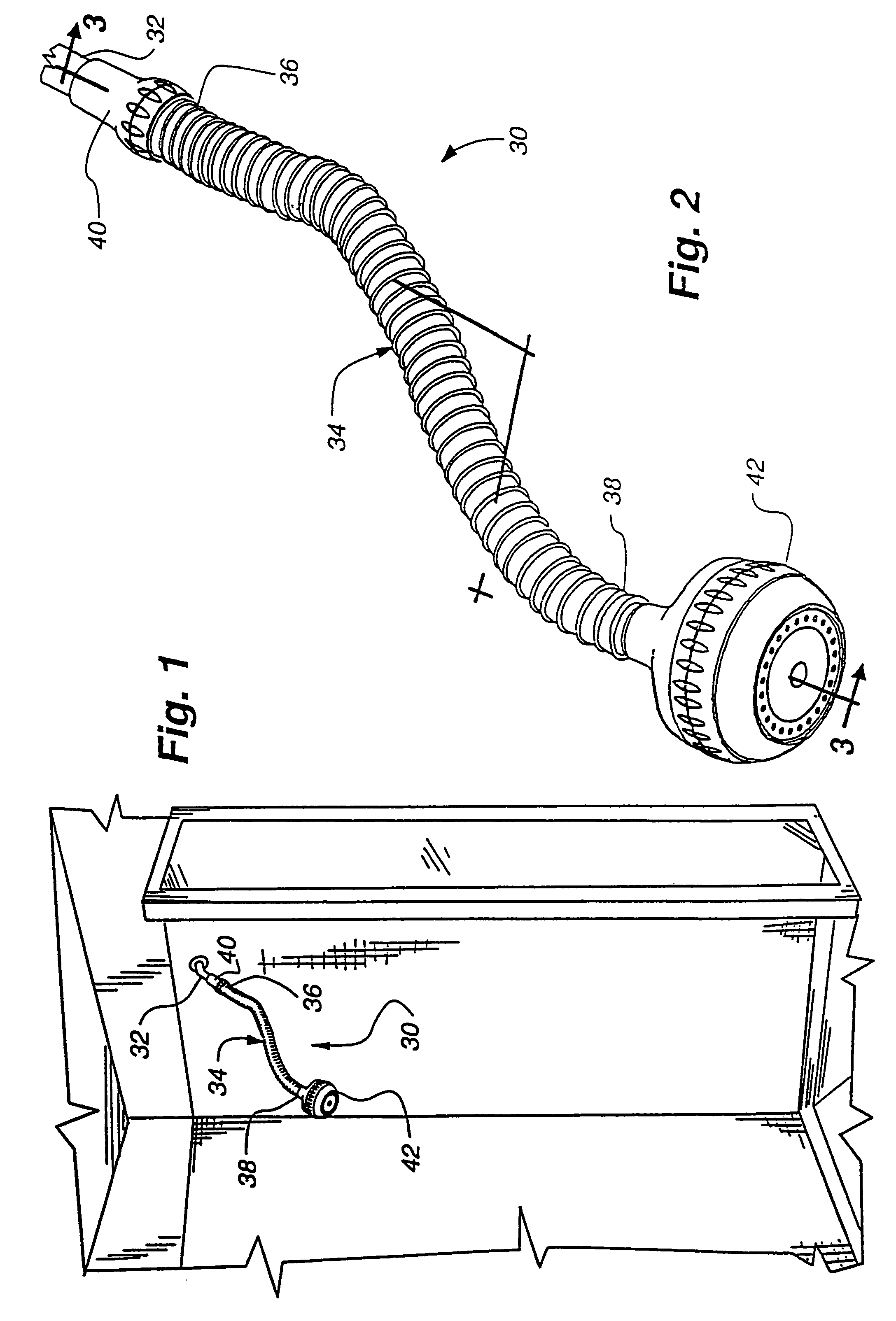
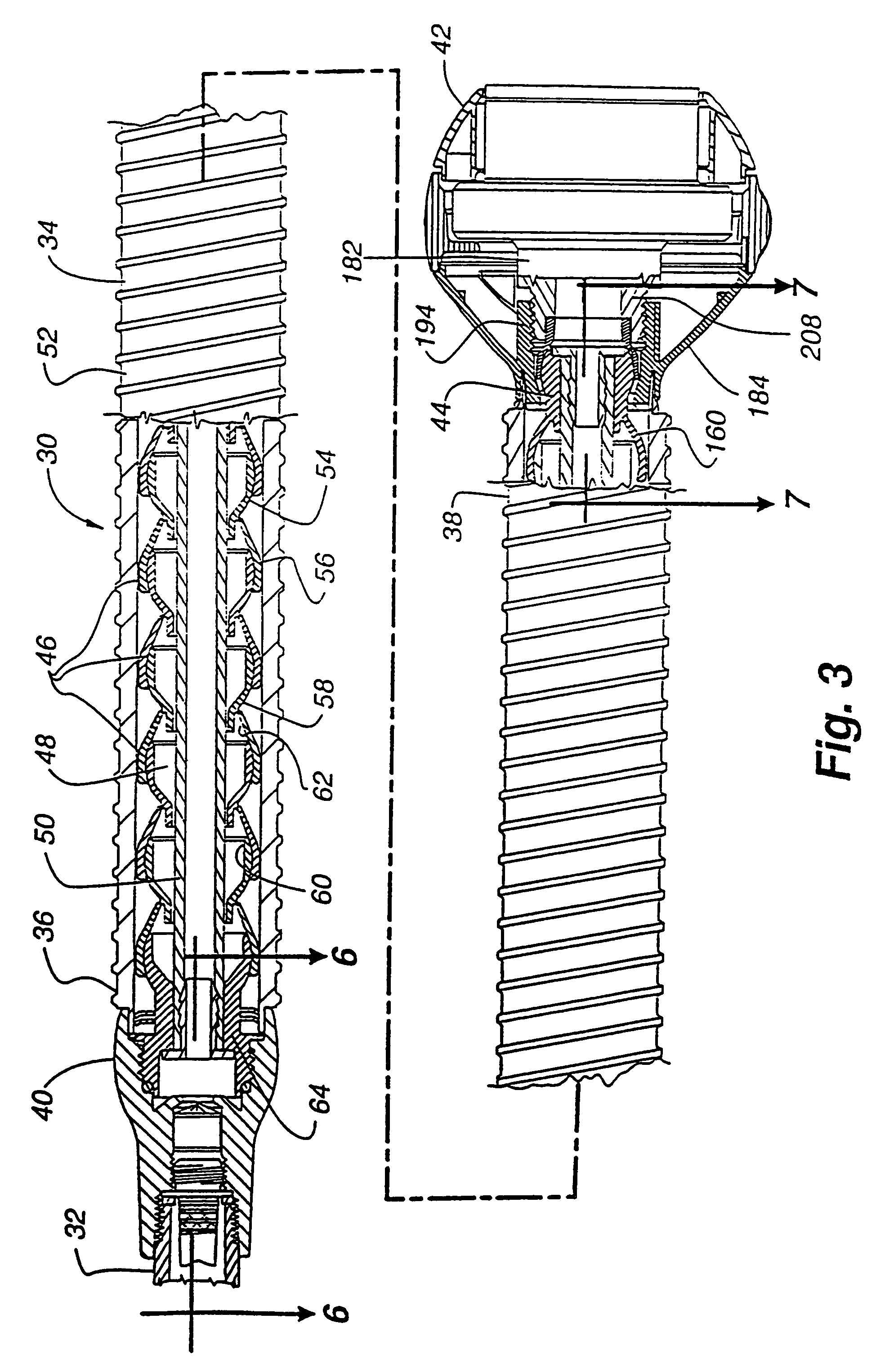
[0029]A shower head assembly 30 encompassing the present invention is shown in FIGS. 1–3. The shower head assembly 30 is attached to a standard shower pipe 32 extending from the wall of a shower stall, as shown in FIG. 1. The shower head assembly 30 includes an elongated flexible shower arm 34 having first 36 and second 38 opposing ends, and defining a water conduit along its entire length. The first end 36 of the flexible shower arm 34 is attached to a shower pipe connector nut 40. The shower pipe connector nut 40 is in turn attached to the standard shower pipe 32 extending from the wall of the shower stall. The second end 38 of the flexible shower arm 34 is adapted to receive a shower head 42. A special connection structure 44 (see FIG. 3) is used between the second end 38 of the flexible shower arm 34 and the shower head 42.

[0030]In use, water flows from the shower pipe 32 through the shower pipe connector nut 40, and into the flexible shower arm 34. The water flows through the c...


PUM


Abstract

A flexible shower arm assembly that allows the user to repeatably adjust the position of the shower head in three dimensions by configuring the shape of the shower arm attached between the water source, such as a shower pipe, and the water dispenser, such as a shower head. The particular position of the shower head, and the direction of the shower spray, can be modified by re-configuring the shape of the shower arm. The flexible shower arm holds the desired position until modified by the user. The flexible shower arm is sealingly attached to the shower pipe by a pipe connector nut, and is sealingly and pivotally attached to the shower head by a connection structure. The flexible shower arm assembly includes an elongated flexible member defining a fluid transfer path, the flexible member having a first end and an opposite second end. The first end of the flexible member is connected in fluid communication with the shower pipe, and the second end of the flexible member is connected in fluid communication to a shower head. A sheath covers the flexible arm from the first end to the second end.

Description

CROSS REFERENCE TO RELATED APPLICATIONS[0001]This application is a continuation of U.S. patent application Ser. No. 09 / 615,299, filed Jul. 13, 2000 now U.S. Pat. No. 6,629,651 and entitled “Flexible Shower Arm Assembly,” which in turn is a continuation of U.S. patent application Ser. No. 09 / 241,345, filed Feb. 1, 1999 and entitled “Flexible Shower Arm Assembly,” now issued as U.S. Pat. No. 6,164,569, which in turn is a continuation of U.S. patent application Ser. No. 08 / 781,863, filed Jan. 10, 1997 and entitled “Flexible Shower Arm Assembly,” now issued as U.S. Pat. No. 5,865,378, all of which are incorporated by reference herein in their entirety.BACKGROUND[0002]1. Field of Invention[0003]This invention relates to a flexible shower arm assembly, and more particularly to a shower arm assembly having a flexible shower arm to allow for flexible adjustment of the position of the shower head.[0004]2. Background Art[0005]Bathing in a shower has replaced bathing in a bathtub as the prefer...

Claims


Application Information

Patent Timeline
Patent Type & Authority Patents(United States)
IPC IPC(8): B05B15/08A47K3/28B05B1/18B05B15/06B05B15/68E03C1/06
CPCB05B1/18E03C1/021E03C1/025E03C1/0408E03C1/06F16L11/18F16L27/047B05B15/652B05B15/654F16L15/08F16L27/073
Inventor MALE, ROBERT B.HOLLINSHEAD, MILTON B.
Owner WATER PIK INC
Why Eureka
Try Eureka