Device with retractable anti-roll means, and use thereof in wire dispensing reels

Inactive Publication Date: 2006-06-27
THERMOCOMPACT
View PDF2 Cites 15 Cited by
  • Summary
  • Abstract
  • Description
  • Claims
  • Application Information

AI Technical Summary

Benefits of technology

[0026]A device with anti-rolling means can advantageously be

Problems solved by technology

This results in a risk of the reel falling off or of unintentional dispensing of the wire.
This results in a risk of irregular dispensing of the wire from the reel when the latter is used afterward on the spark erosion machine, and such irregularities can interfere with the operation of the spark erosion machine, to the point of complete stoppage of the machine, which necessitates the intervention of an operator.
However, the reel then no longer conforms

Method used


Image

  • Device with retractable anti-roll means, and use thereof in wire dispensing reels
  • Device with retractable anti-roll means, and use thereof in wire dispensing reels
  • Device with retractable anti-roll means, and use thereof in wire dispensing reels

Examples


Example

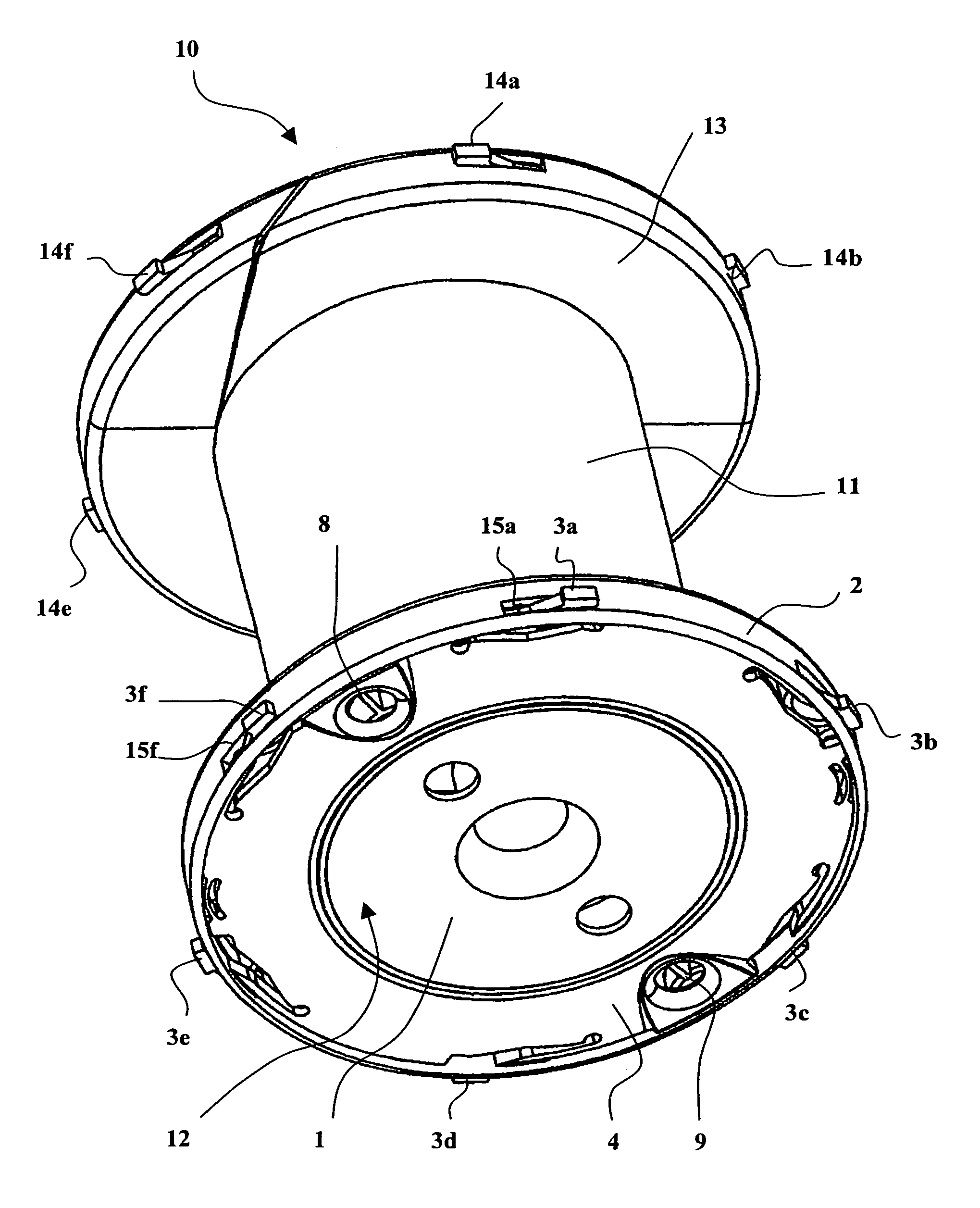
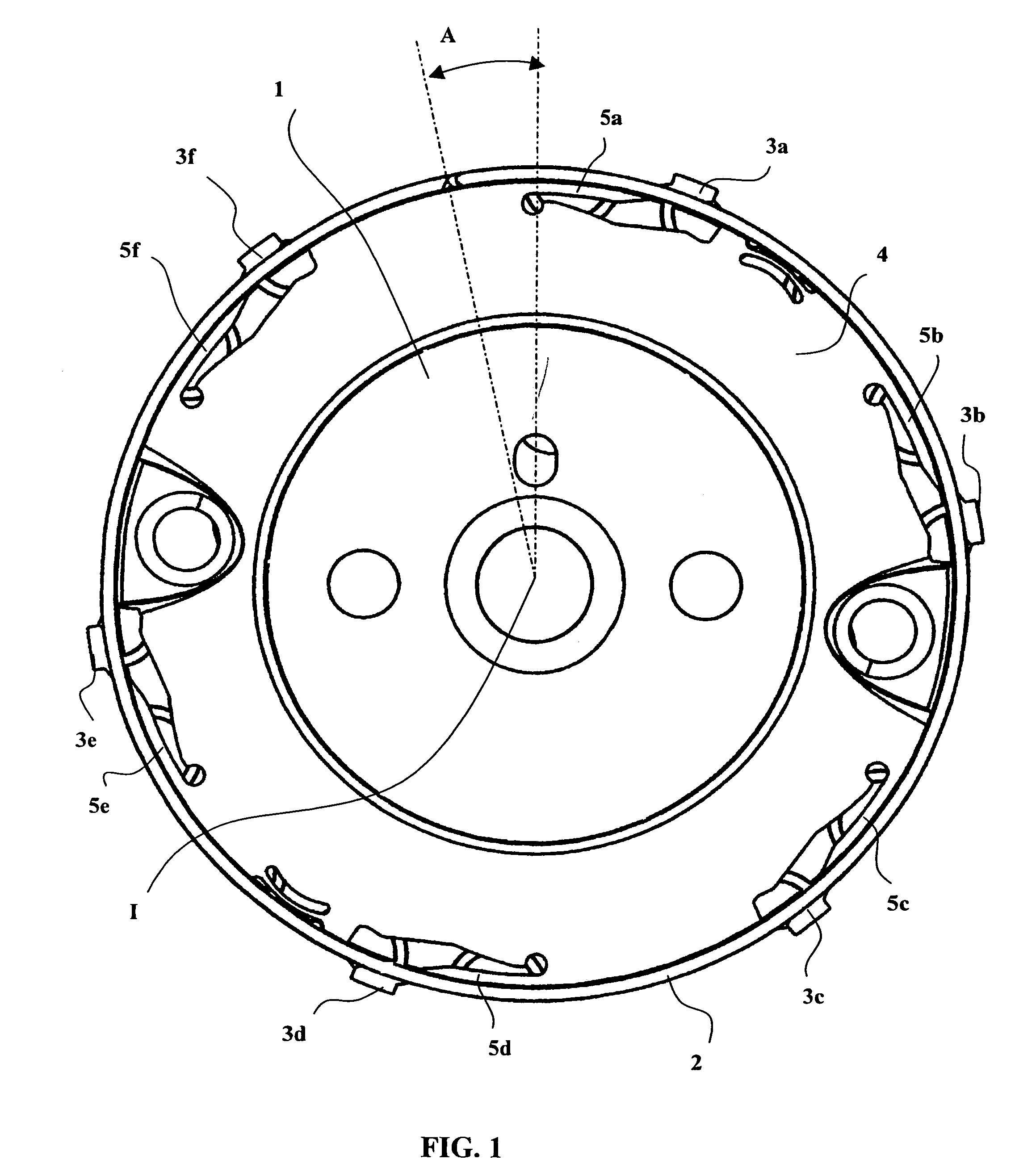
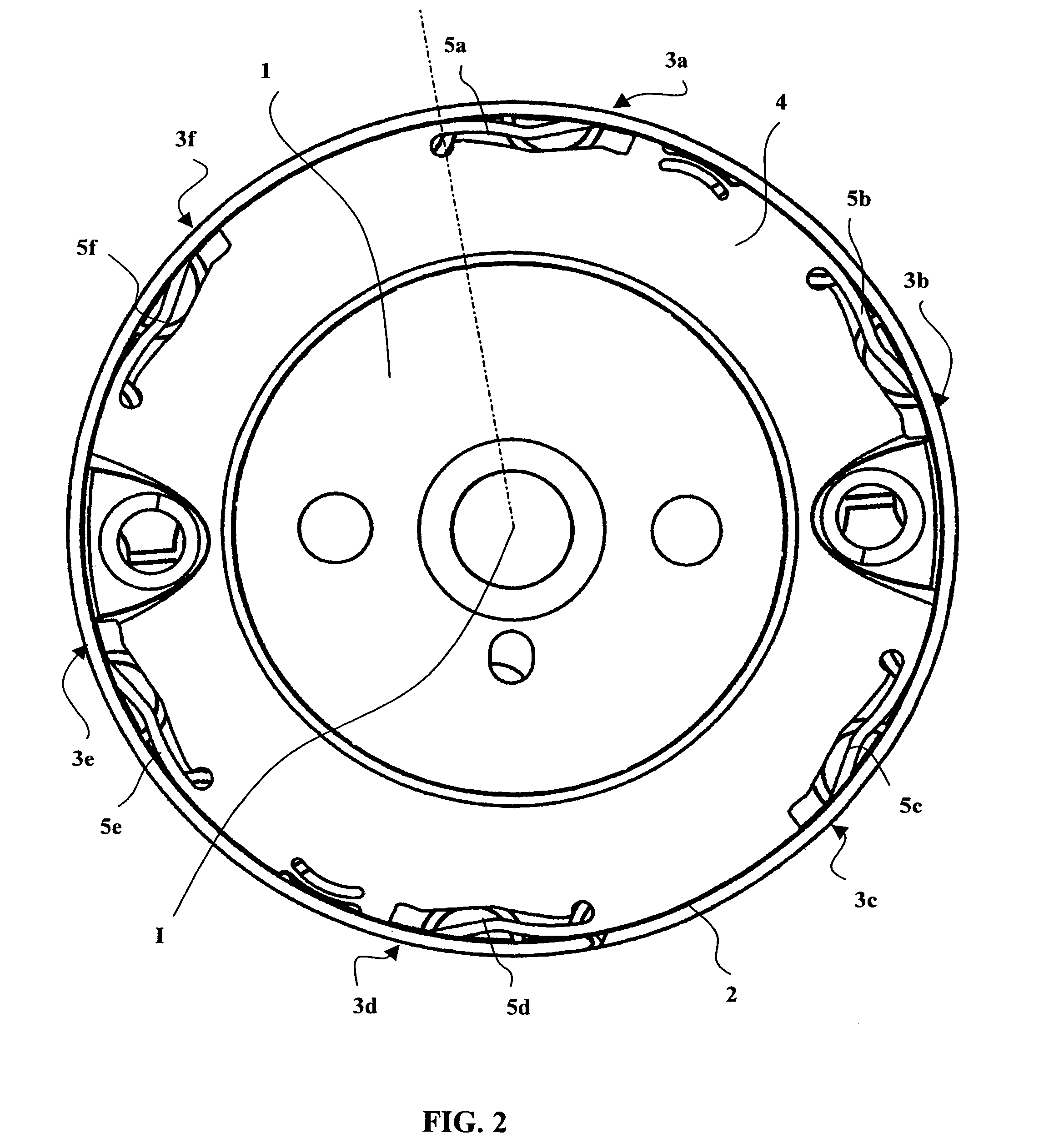
[0038]In the embodiment of FIGS. 1 to 4, a device in accordance with the invention with anti-rolling means comprises a rolling flange 1 delimited by a circular peripheral rolling edge 2 provided with radial anti-rolling projections such as the projections 3a, 3b, 3c, 3d, 3e and 3f. In the projecting position shown in FIG. 1, the radial anti-rolling projections 3a–3f project radially from the peripheral rolling edge 2, whereas in FIG. 3 the radial anti-rolling projections are not visible because they are entirely retracted to allow rolling of the rolling flange 1 on its peripheral rolling edge 2.

[0039]The radial anti-rolling projections 3a to 3f are moved radially, between their FIG. 1 projecting position and their FIG. 2 retracted position, by a coaxial controlling ring 4 mounted on the rolling flange 1 to rotate about the axis I of said flange. For example, the coaxial controlling ring 4 is mounted on the anterior face of the rolling flange 1 so that it can rotate through a rotatio...


PUM


Abstract

The invention a device with retractable anti-roll means designed in particular for a wire dispensing reel (10) having a cylindrical body (11) and end flanges (12, 13). The end flange (12) comprises a circular peripheral rolling edge (2) provided with slots (15a–15f) wherein slide elastic blades (5a–5f) the ends of which constitute retractable radial anti-roll projections (3a–3f). The elastic blades (5a–5f) are integral with a coaxially operated ring (4) whereof the rotation enables to project or retract the radial anti-roll projections (3a–3f). Thus it is possible to selectively allow the reel to turn by retracting the radial anti-roll projections (3a–3f), or to lock the reel in rotation by extending the radial anti-roll projections (3a–3f)

Description

TECHNICAL FIELD OF THE INVENTION[0001]This is a U.S. National Phase of International Application No. PCT / FR02 / 02579 filed Jul. 19, 2002.[0002]The present invention relates to means for controlling and adapting the rolling capacities of a rolling flange delimited by a peripheral rolling edge.[0003]The invention finds an application in wire dispensing reels in particular, in which the rolling capacity of the reel on the peripheral edges of its end flanges can be controlled and modified.[0004]The invention stems from observing the conditions of use of wire dispensing reels and in particular spark erosion electrode wire dispensing reels.[0005]For use in spark erosion machines, the electrode wire is packaged on a reel comprising a cylindrical body flanked by two end flanges of larger diameter with a circular rolling edge. The circular shape of the rolling edges of the end flanges is rendered mandatory by the applicable standards, and allows the reel to turn freely when it is being filled...

Claims


Application Information

Patent Timeline
IPC IPC(8): B65H75/12B65H75/18B65H75/14B65H75/30
CPCB65H75/18B65H75/14
Inventor CORNIER, JEAN-CLAUDEMOLLARD, GILLES
Owner THERMOCOMPACT
Why Eureka
Try Eureka