
Protective unit to prevent contact with conductive contacts in a withdrawable space of switching device

a protection unit and switching device technology, applied in the field of electric switches, can solve problems such as blocking the lever system on the second and/or third stop surfa

Inactive Publication Date: 2006-06-27
SIEMENS AG
View PDF10 Cites 11 Cited by
  • Summary
  • Abstract
  • Description
  • Claims
  • Application Information

AI Technical Summary

Benefits of technology

[0005]The present invention is based on an object of configuring the lever arrangement in such a way that, after release of the access openings to the contacts, it is not necessary to slide the lever arrangement out of the path of movement of the switching device using the force of the moving-in switching device.
[0006]An object of the present invention is achieved according to the present invention by the linking joint of the two levers simultaneously forming the pivot bearing of the first lever, by the first lever having a slide block and by there being formed in the withdrawable rack two guiding surfaces which form a for the slide block, running in a graded manner in the pivoting direction of the first lever, wherein one of the two guiding surfaces form two stepping stages for the slide block, which are allocated to the two pushing-in phases and run substantially in the direction of displacement of the first lever, and wherein the setting stage, connecting the two stepping stages, runs in the pivoting direction of the first lever and forms a stop surface allocated to the slide block.—On account of a configuration of this type, the first lever can be pivoted into an end position shortly after release of the access openings from the path of movement of the switching device. The decoupling of the end of the first lever allocated to the switching device from the switching device allows damage to the lever system to be reliably ruled out when the switching device moves into its end position.
[0008]For operating the first lever there may advantageously be provided a forming cam, which is allocated to the free end of the first lever arm, is carried by the switching device and has a first working surface, which is inclined in the pushing-in direction of the switching device and by way of which the first lever is displaceable in the region of the first stepping stage and, at the end of the first stepping stage, is pivotable, making itself lie adjacent to the first setting stage.—As a result, raising of the protective plate in a way corresponding to the inclination of the working surface over just a few millimeters of the path of movement of the switching device is possible shortly before contacts protruding on the rear side of the switching device engage in the access openings of the cover plate.

Problems solved by technology

On the other hand, any force acting on the first lever in another direction, for example during assembly work, leads to the blocking of the lever system on the second and / or third stop surface.

Method used


Image

  • Protective unit to prevent contact with conductive contacts in a withdrawable space of switching device
  • Protective unit to prevent contact with conductive contacts in a withdrawable space of switching device
  • Protective unit to prevent contact with conductive contacts in a withdrawable space of switching device

Examples


Embodiment Construction

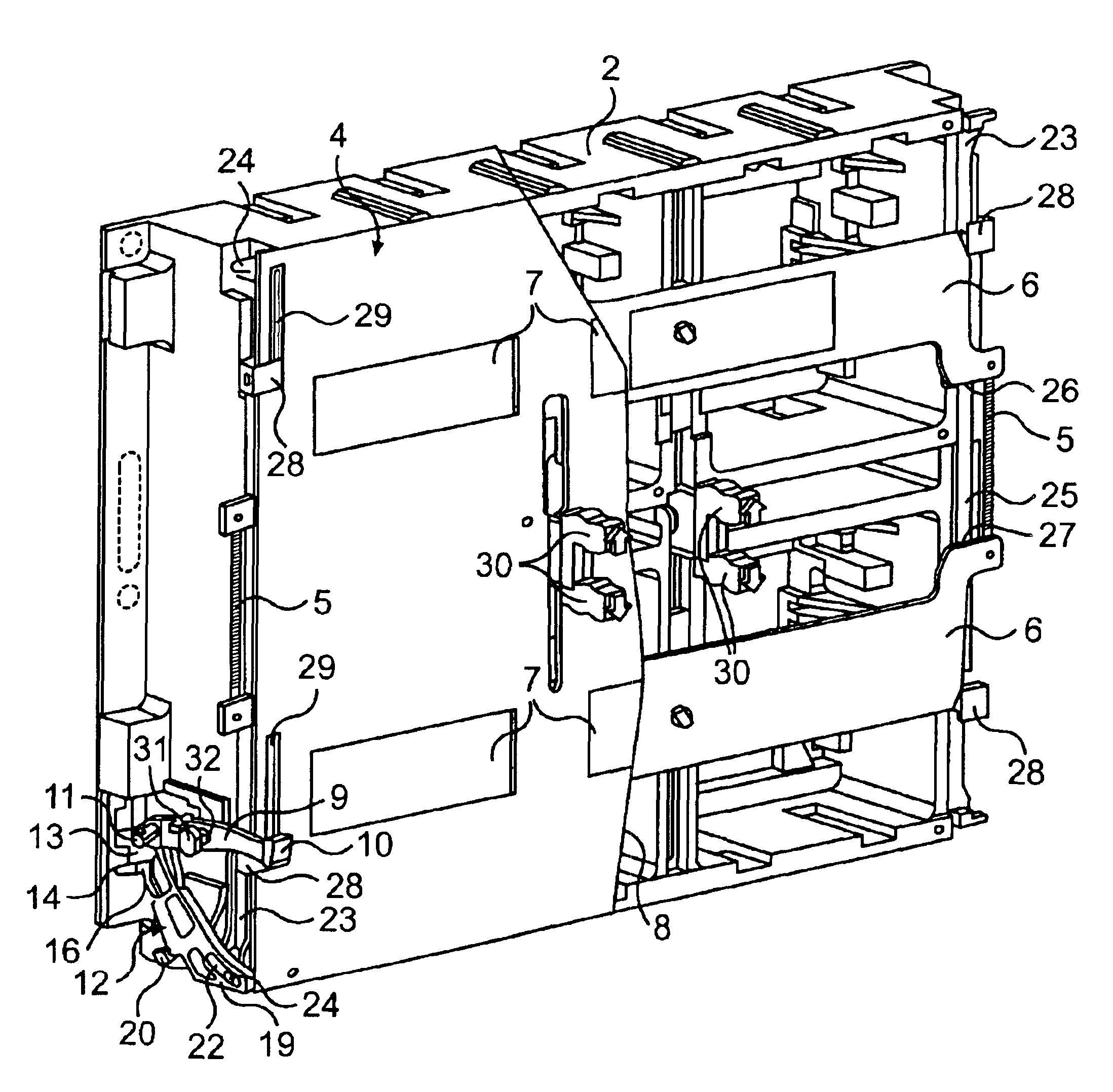
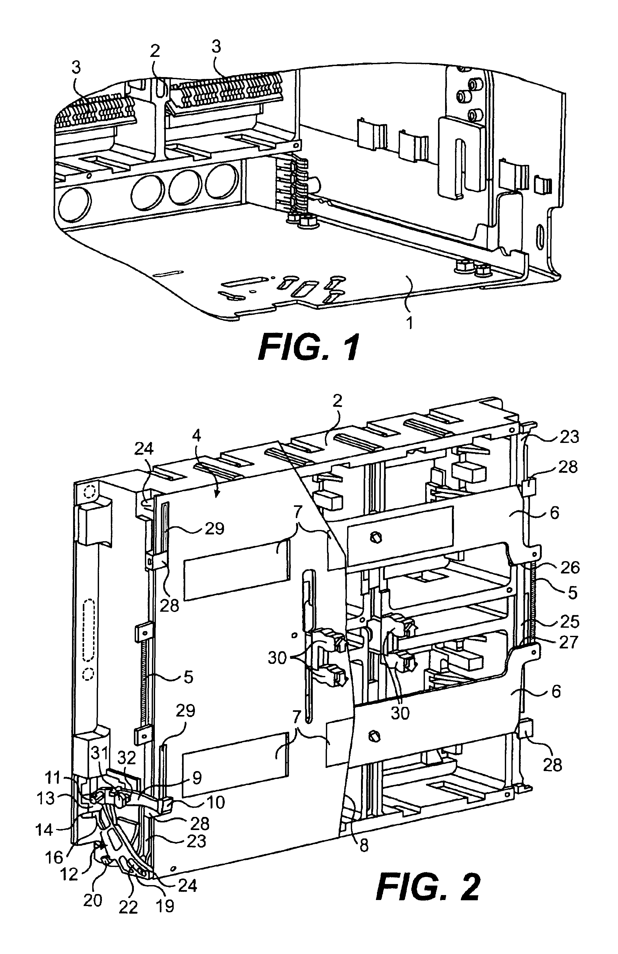
[0021]The withdrawable rack 1 shown in FIG. 1 is provided with an isolating contact housing 2, which serves for receiving conductive contacts, of which incoming and outgoing contacts are arranged in a way not represented any further in planes arranged one above the other.

[0022]According to FIG. 2, a protective unit 4 is mounted on the isolating contact housing 2 to prevent contact with conductive contacts 3. In this case, the protective unit 4 has two movable protective plates 6, which are allocated to contacts arranged in two planes and are coupled by means of two tension springs 5, a cover plate 8, which is provided with access openings 7 with respect to the contacts, and also two identically designed lever arrangements for operating the protective plates.

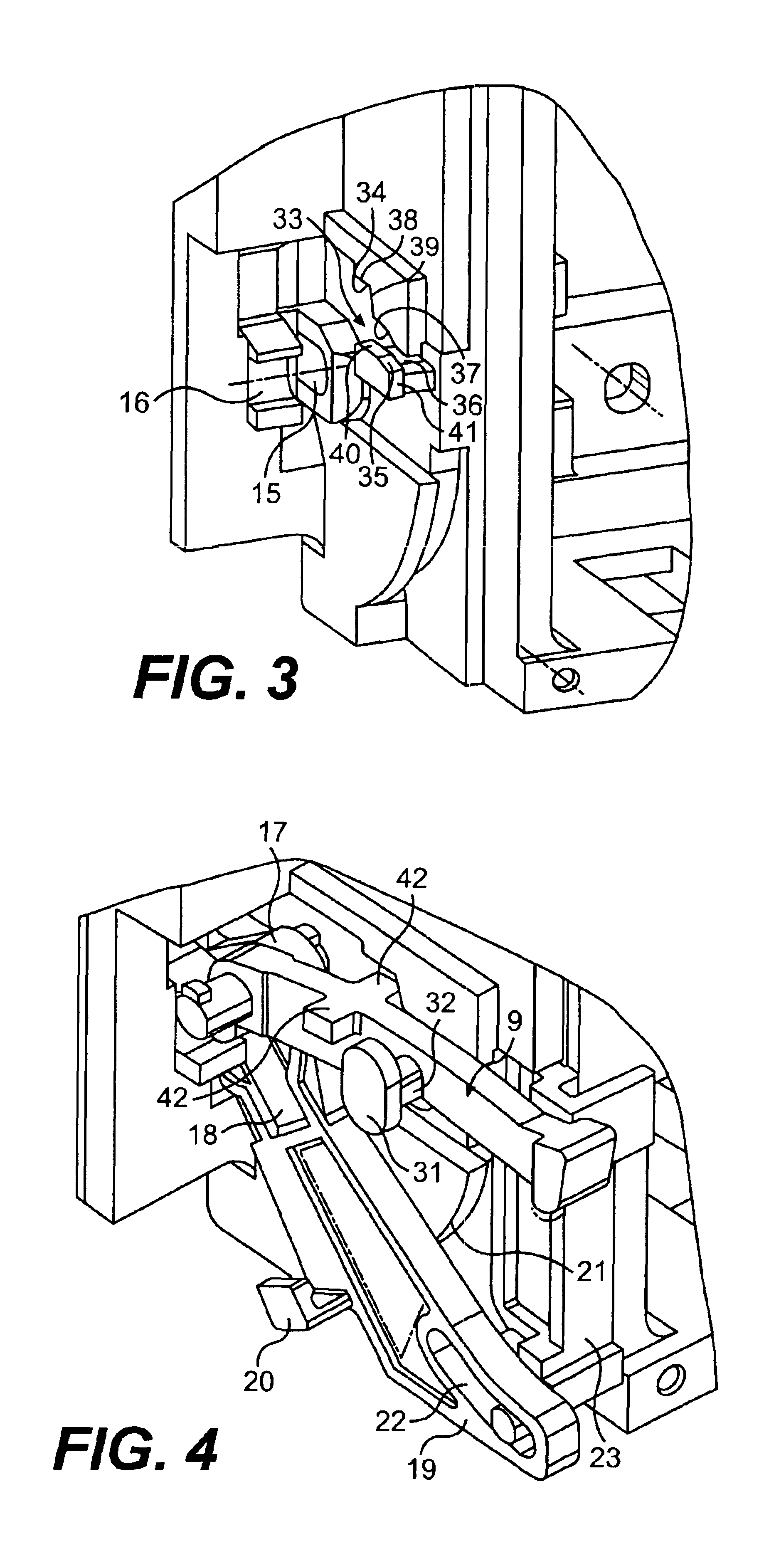
[0023]Each of the two lever arrangements has three levers, of which a first lever 9 can be operated at a free end 10 by means of switching device. The other end of the first lever 9 is articulated by means of a linking joint 11 o...


PUM


Abstract

A protective unit may prevent contact with conductive contacts in a withdrawable rack of a switching device. This may include one displaceable protective plate and lever arrangement for operating the protective plate. The lever arrangement has two levers that are interconnected in an articulated manner, of which a first lever can be operated by way of the switching device and the second lever is coupled to the mobile protective plate. A linking joint of the two levers acts simultaneously as the pivot bearing of the first lever and the first lever can be pivoted out of the displacement path of the switching device into an end position by way of a slide block that runs in a graded manner in the pivoting direction of the first lever.

Description

[0001]This application is the national phase under 35 U.S.C. § 371 of PCT International Application No. PCT / DE02 / 01464 which has an International filing date of Apr. 18, 2002, which designated the United States of America and which claims priority on German Patent Application number DE 101 20 749.2 filed Apr. 23, 2001, the entire contents of which are hereby incorporated herein by reference.FIELD OF THE INVENTION[0002]The present invention generally relates to electrical switches used for the configuration of a withdrawable rack for a displaceably arranged switching device, in which a protective unit is provided to prevent contact with conductive contacts.BACKGROUND OF THE INVENTION[0003]In the case of a known withdrawable rack, a protective unit with two movable protective plates—which are displaceable for the release of access openings formed in a cover plate with respect to incoming and outgoing contacts—and two lever arrangements for operating the two protective plates is provid...

Claims


Application Information

Patent Timeline
Patent Type & Authority Patents(United States)
IPC IPC(8): H01H9/20H02B11/24
CPCH02B11/24
Inventor DEYLITZ, ERHARDMAREK, KATHRINA
Owner SIEMENS AG
Learn More