Method for producing fuel cell membrane electrode assembly

a fuel cell membrane and electrode assembly technology, applied in the direction of cell components, final product manufacturing, sustainable manufacturing/processing, etc., can solve the problems of achieve the effect of reliably suppressing damage to the electrolyte membran

Active Publication Date: 2018-11-27
HONDA MOTOR CO LTD
View PDF10 Cites 0 Cited by
  • Summary
  • Abstract
  • Description
  • Claims
  • Application Information

AI Technical Summary

Benefits of technology

[0013]The present invention has an object of providing a method for producing a fuel cell membrane electrode assembly that can prevent a required catalyst layer from being removed, while suppressing damage to the electrolyte membrane.
[0015]In the present invention, first, after bonding the catalyst layer-including substrate only to one face of the electrolyte membrane, the unwanted portion is removed by cutting using energy rays such as a laser beam that penetrates the electrolyte membrane without penetrating the catalyst layer-including substrate and peeling, and subsequently the catalyst layer is formed on the other face. Since the catalyst layer is formed on the other face after cutting in a predetermined shape and removing in this way, this catalyst layer will not be removed by the energy rays penetrating the electrolyte membrane. Therefore, according to the present invention, it is possible to prevent the required catalyst layer from being removed while suppressing damage to the electrolyte film.
[0017]In the present invention, first, after bonding the catalyst layer-including substrate only to one face of the electrolyte membrane, the unwanted portion is directly removed using energy rays such as a laser beam that penetrates the electrolyte membrane without penetrating the catalyst layer-including substrate, and subsequently forms the catalyst layer on the other face. Since the catalyst layer is formed on the other face after removing in a predetermined shape in this way, this catalyst layer will not be removed by the energy rays penetrating the electrolyte membrane. Therefore, according to the present invention, it is possible to prevent the required catalyst layer from being removed while suppressing damage to the electrolyte film.
[0019]The present invention uses a laser beam having transmittance relative to the electrolyte membrane of at least 80%. It is thereby possible to more reliably suppress damage to the electrolyte membrane by using high-transmittance energy rays.
[0020]According to the present invention, it is possible to provide a method for producing a fuel cell membrane electrode assembly that can prevent a required catalyst layer from being removed, while suppressing damage to the electrolyte membrane.

Problems solved by technology

However, if the absorbance of this laser to the electrolyte membrane is high, it will cause damage to the electrolyte membrane.

Method used


Image

  • Method for producing fuel cell membrane electrode assembly
  • Method for producing fuel cell membrane electrode assembly
  • Method for producing fuel cell membrane electrode assembly

Examples


first embodiment

[0026](First Embodiment)

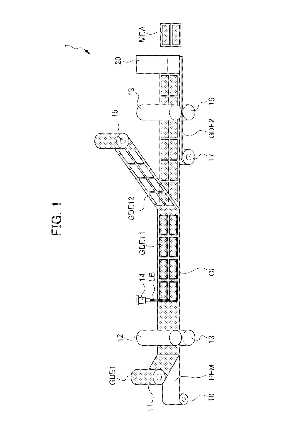
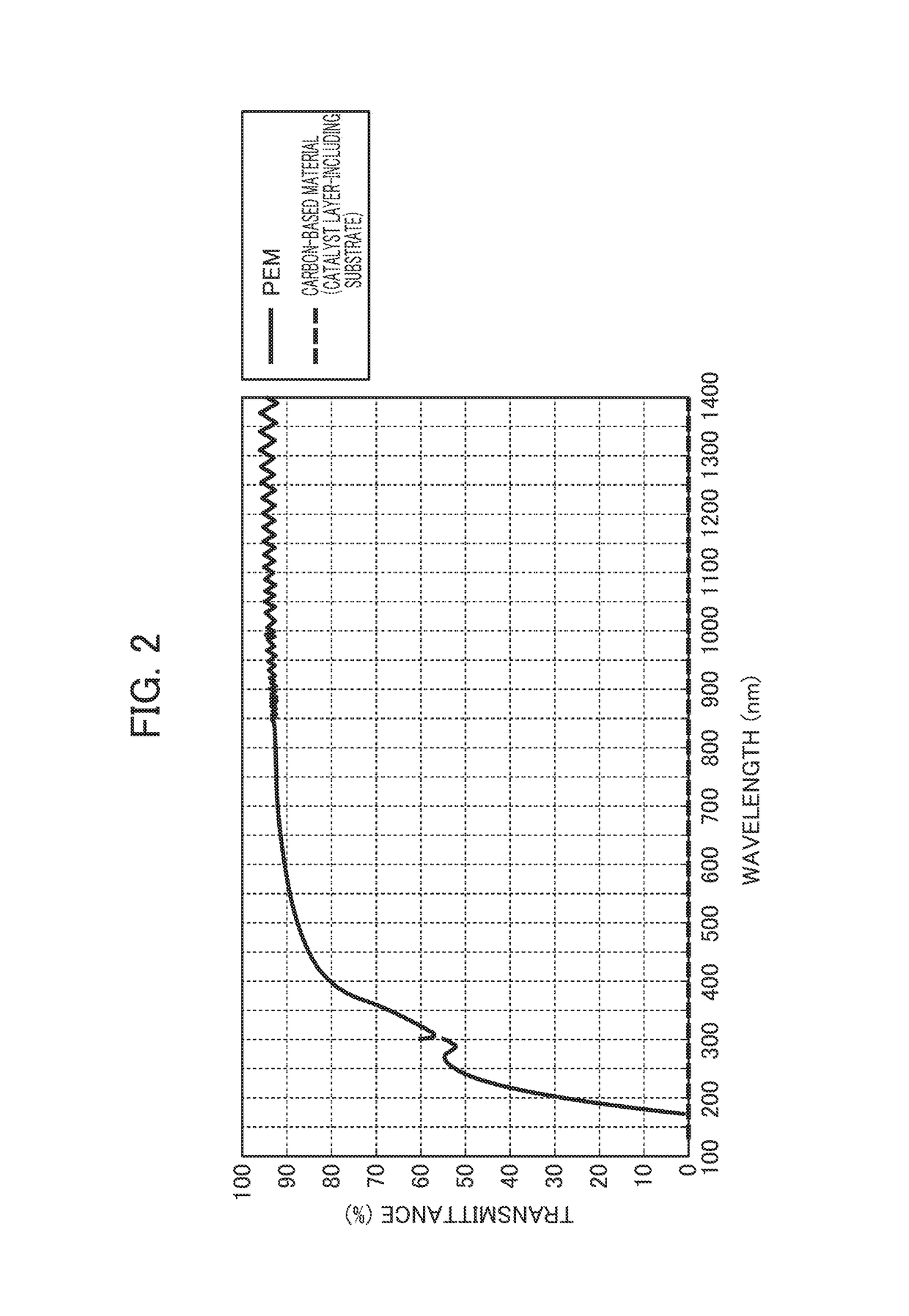
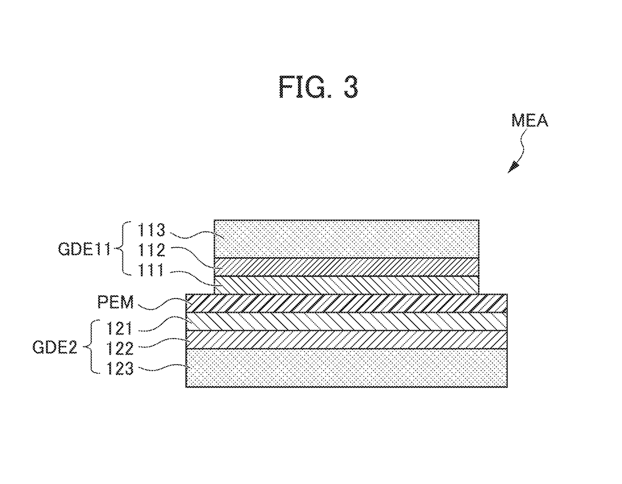
[0027]FIG. 1 is a schematic view showing a production line 1 of a membrane electrode assembly MEA for a fuel cell according to the embodiment of the present invention. FIG. 2 is a graph showing a relationship between wavelength and transmittance of a laser beam LB of a second laser device 14. FIG. 3 is a cross-sectional view of a fuel cell membrane electrode assembly MEA produced.

[0028]The production line 1 of the fuel cell membrane electrode assembly (Membrane Electrode Assembly) MEA shown in FIG. 1 raises the production efficiency of the fuel cell membrane electrode assembly MEA by making continuous with a roll-to-roll method. More specifically, the production line 1 of the fuel cell membrane electrode assembly MEA includes: an electrolyte membrane roll 10; a first substrate roll 11; a pair of upper / lower temporary bonding rolls 12, 13; a laser device 14; a recovery roll 15; a second substrate roll 17; a pair of upper / lower bonding rolls 18, 19; a cutter 20...

second embodiment

[0056](Second Embodiment)

[0057]FIG. 4 is a schematic view showing a production line 2 of a fuel cell membrane electrode assembly MEA according to a second embodiment of the present invention. It should be noted that the production line 2 according to the present embodiment is the same configuration as the production line 1 of the aforementioned first embodiment, except for the processing on the unwanted portion GDE12 of the first catalyst layer-including substrate GDE1 differing from the aforementioned production line 1.

[0058]The production line 2 of the fuel cell membrane electrode assembly MEA shown in FIG. 4 includes a first substrate roll 11, a pair of upper / lower temporary bonding rolls 12, 13, a laser device 24, a second substrate roll 17, a pair of upper / lower bonding rolls 18, 19, a cutter 20, etc. In other words, contrary from the aforementioned production line 1, the production line 2 and does not include a recovery roll 15, while including the laser device 24 in place of ...


PUM

PropertyMeasurementUnit
transmittanceaaaaaaaaaa
wavelengthaaaaaaaaaa

Abstract

A method for producing a fuel cell membrane electrode assembly includes: a step of bonding a polymer electrolyte membrane and a first catalyst layer-including substrate; a step of making a cut by way of a laser beam so that the first catalyst layer-including substrate bonded with the polymer electrolyte membrane becomes a predetermined shape; a step of peeling an unwanted portion of the first catalyst layer-including substrate from the polymer electrolyte membrane; and a step of forming a second catalyst layer on the other face of the polymer electrolyte membrane, and punching out the polymer electrolyte membrane and second catalyst layer so that the first catalyst layer-including substrate of the predetermined shape bonded on one face is surrounded, in which the laser beam has a wavelength that penetrates the polymer electrolyte membrane without penetrating the first catalyst layer-including substrate.

Description

[0001]This application is based on and claims the benefit of priority from Japanese Patent Application No. 2016-055712, filed on 18 Mar. 2016, the content of which is incorporated herein by reference.BACKGROUND OF THE INVENTION[0002]Field of the Invention[0003]The present invention relates to a method for producing a fuel cell membrane electrode assembly in which electrode layers are laminated on both surfaces of an electrolyte membrane.[0004]Related Art[0005]The membrane electrode assembly (MEA) of a fuel cell has a structure made by a catalyst layer and diffusion layer (collectively “electrode layer”) being laminated on both surfaces to sandwich an electrolyte membrane, as described in Patent Document 1, for example. In addition, one electrode layer, in order to assume a creepage distance for ensuring insulation between the electrode layers on both surfaces, is configured so that the electrolyte membrane is exposed at the peripheral edge.[0006]As a method of producing such an MEA,...

Claims


Application Information

Patent Timeline
Patent Type & Authority Patents(United States)
IPC IPC(8): H01M4/88B32B38/10B32B37/14H01M8/1018
CPCH01M4/8825B32B37/14B32B38/10H01M4/8875H01M4/881H01M2008/1095B32B2457/18H01M4/88H01M8/1004B32B38/0004B32B2310/0843Y02E60/50Y02P70/50
Inventor YOKOI, MAIMATSUO, KAZUHIDEKONISHI, SHUNSUKEHORI, YUICHIMUROMOTO, NOBUYOSHI
Owner HONDA MOTOR CO LTD
Why Eureka
Try Eureka