Sheet depositing arrangement

a deposit arrangement and sheet technology, applied in the direction of thin material processing, article separation, article delivery, etc., can solve the problems of the entire plant being stopped, at least one sheet or the deposit arrangement being damaged

Active Publication Date: 2018-06-07
BHS CORRUGATED MASCHEN & ANLAGENBAU
View PDF10 Cites 0 Cited by
  • Summary
  • Abstract
  • Description
  • Claims
  • Application Information

AI Technical Summary

Benefits of technology

[0029]It is advantageous, in a sheet depositing arrangement where the sheet stacking region is bounded by at least two deflection rollers for guiding the sheet transporting means, wherein, in particular, at least the upstream one of these deflection rollers with regard to the direction of circulation is arranged directly adjacent to the sheet stacking chamber, for the deflection rollers for forming the sheet stacking region to have a small diameter, in particular a smaller diameter than the other rollers of the sheet extraction device. Favourably, the upstream one of these deflection rollers, with regard to the direction of circulation, has a diameter of between 1 cm and 20 cm, more preferably between 2 cm and 7 cm, in order to form a knife edge. Said upstream roller fivourably forms a knife-edge deflection roller. The other of these deflection rollers preferably has a diameter of between 5 cm and 30 cm, more preferably between 6 cm and 10 cm. This roller favourably forms a knife-edge deflection roller. The sheets are thus able to be guided in the sheet stacking region for a particularly long time.

Problems solved by technology

A disadvantage of these sheet depositing arrangements is that, while the sheets are being stacked, faults sometimes occur which can result in at least one sheet or the sheet depositing arrangement being damaged.
A stoppage of the entire plant can also be the result.

Method used


Image

  • Sheet depositing arrangement
  • Sheet depositing arrangement
  • Sheet depositing arrangement

Examples


Embodiment Construction

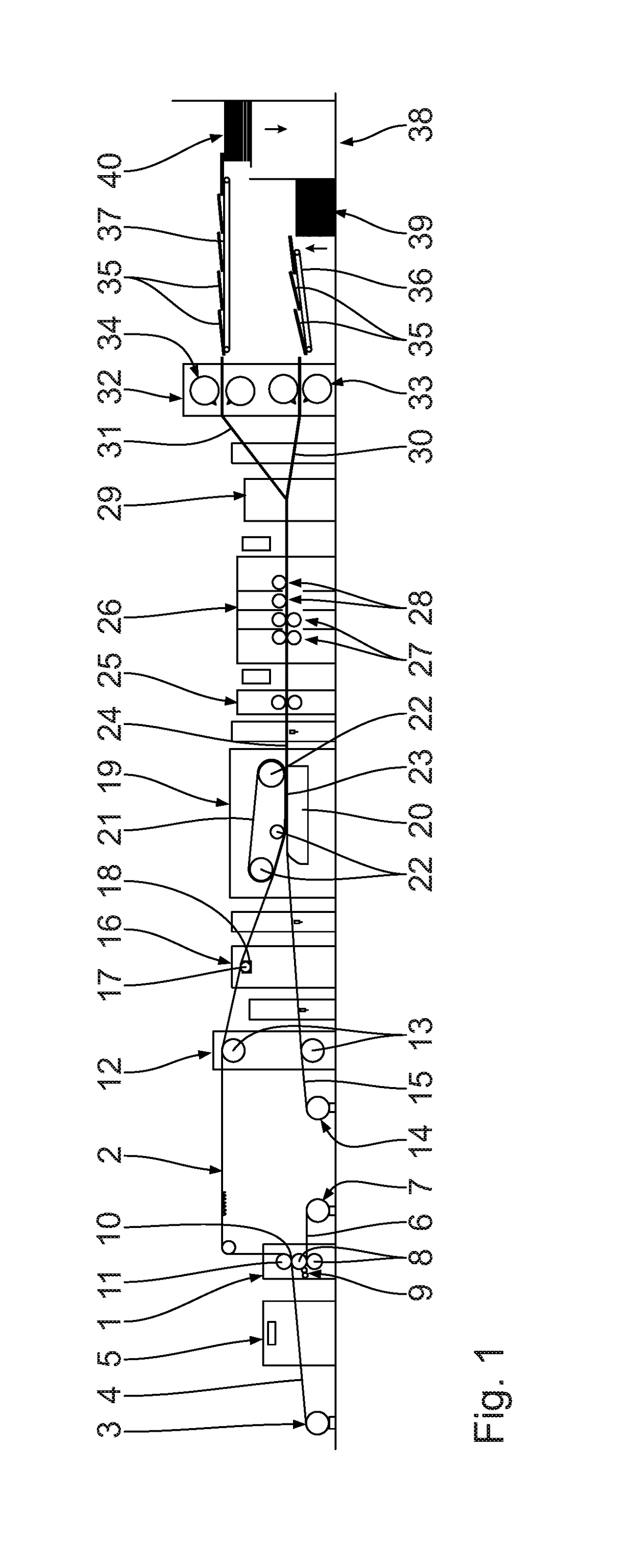
[0037]With reference first of all to FIG. 1, a corrugated-board plant illustrated therein comprises a machine 1 for producing a corrugated-board web 2 laminated on one side.

[0038]A first unrolling device 3 feeds a first, preferably endless, material web 4 via a preheating device 5 to the machine 1 for producing the corrugated-board web 2 that is laminated on one side. The first material web 4 represents a top web for the corrugated-board web 2 laminated on one side that is produced in the machine 1 for producing the corrugated-board web 2 laminated on one side.

[0039]The first material web 4 is combined, in the machine 1 for producing the corrugated-board web 2 laminated on one side, with a second, preferably endless, material web 6 which is unrolled from a second unrolling device 7.

[0040]In the machine 1 for producing the corrugated-board web 2 laminated on one side, the second material web 6 is guided through between two fluted rollers 8, arranged adjacent to one another, in order ...


PUM


Abstract

The invention relates to a sheet depositing arrangement. The sheet depositing arrangement comprises at least one sheet depositing apparatus having a sheet stacking chamber for creating a sheet stack, and a sheet extraction device which in turn has a sheet transporting means that is drivable in a direction of circulation, a sheet delivery region for delivering the sheets to be stacked to the sheet stacking chamber, a sheet stacking region, provided downstream of the sheet delivery region, for stacking the sheets to be stacked into the sheet stacking chamber, and a return region, provided downstream of the sheet stacking region. Furthermore, the sheet depositing apparatus has a sheet retaining device with at least one sheet retaining element, arranged adjacent to the sheet stacking region, for preventing at least one sheet to be stacked from being drawn into the sheet extraction device from the sheet stacking chamber by the sheet transporting means.

Description

CROSS-REFERENCE TO RELATED APPLICATIONS[0001]This patent application claims priority of German Patent Application Serial No. DE 10 2016 224 408.6 filed on Dec. 7, 2016, pursuant to 35 U.S.C. 1.19 (a)-(d), the content of which is incorporated herein by reference in its entirety as if fully set forth herein.FIELD OF THE INVENTION[0002]The invention relates to a sheet depositing arrangement for depositing sheets, in particular corrugated-board sheets, in sheet stacks. Furthermore, the invention is directed at a sheet transporting means which is in particular part of such a sheet depositing arrangement. The invention is also directed at a plant, in particular a corrugated-board plant, having at least one such sheet depositing arrangement.BACKGROUND OF THE INVENTION[0003]Sheet depositing arrangements are well known from the prior art through public prior use. They serve to deposit or stack sheets in sheet stacks. A disadvantage of these sheet depositing arrangements is that, while the sh...

Claims


Application Information

Patent Timeline
Patent Type & Authority Applications(United States)
IPC IPC(8): B65H29/22B65H31/26B65H31/32
CPCB65H29/22B65H31/26B65H31/32B65H2701/1762B65H3/56B65H29/18B65H29/52B65H31/10B65H2405/113B65H2701/1764B65H29/14B65H29/50B65H31/24B65H2404/262B65H2405/3311B65H29/54B65H29/56B65H29/16
Inventor GRILL, MARTIN
Owner BHS CORRUGATED MASCHEN & ANLAGENBAU
Why Eureka
Try Eureka