Gas-discharge display device and its manufacturing method

a technology of a display device and a manufacturing method, which is applied in the manufacture of electrode systems, cold cathode manufacturing, and electric discharge tubes/lamps, etc., can solve the problems of inability to have an appropriate flatness, dielectric and conductive thick films may be cracked or deformed, and substrates may be distorted

Inactive Publication Date: 2006-06-27
NORITAKE CO LTD
View PDF18 Cites 35 Cited by
  • Summary
  • Abstract
  • Description
  • Claims
  • Application Information

AI Technical Summary

Benefits of technology

[0007]It is therefore an object of the present invention to provide a gas-discharge display apparatus, and a method of producing a gas-discharge display apparatus, each of which is free of the problem of distortions resulting from a heat treatment to form electrodes.

Problems solved by technology

Therefore, in each of the above-described electrode structures, the electrodes are formed on the inner surface of at least one of the front and rear plates (i.e., substrates), by using, e.g., the thick-film forming process in which the substrates are subjected to the heat treatment so as to fire the thick films, and accordingly the substrates may be distorted and the dielectric and conductive thick films may be cracked or deformed.
If the substrates are thus distorted, then they cannot have an appropriate flatness and / or the thick-film patterns cannot have an appropriate accuracy.

Method used


Image

  • Gas-discharge display device and its manufacturing method
  • Gas-discharge display device and its manufacturing method
  • Gas-discharge display device and its manufacturing method

Examples


first embodiment

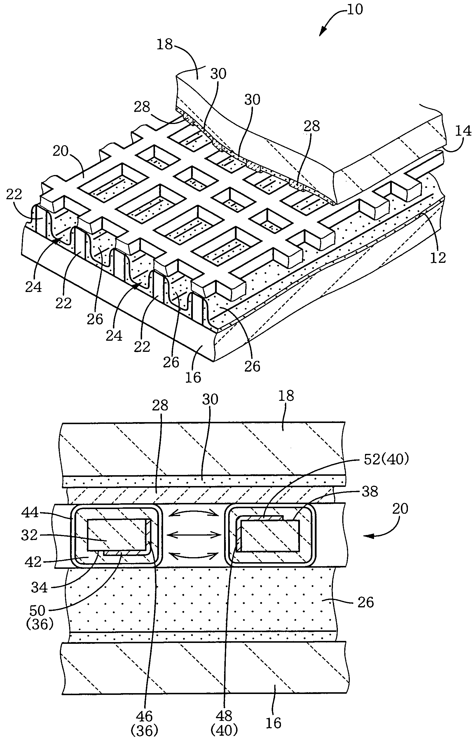
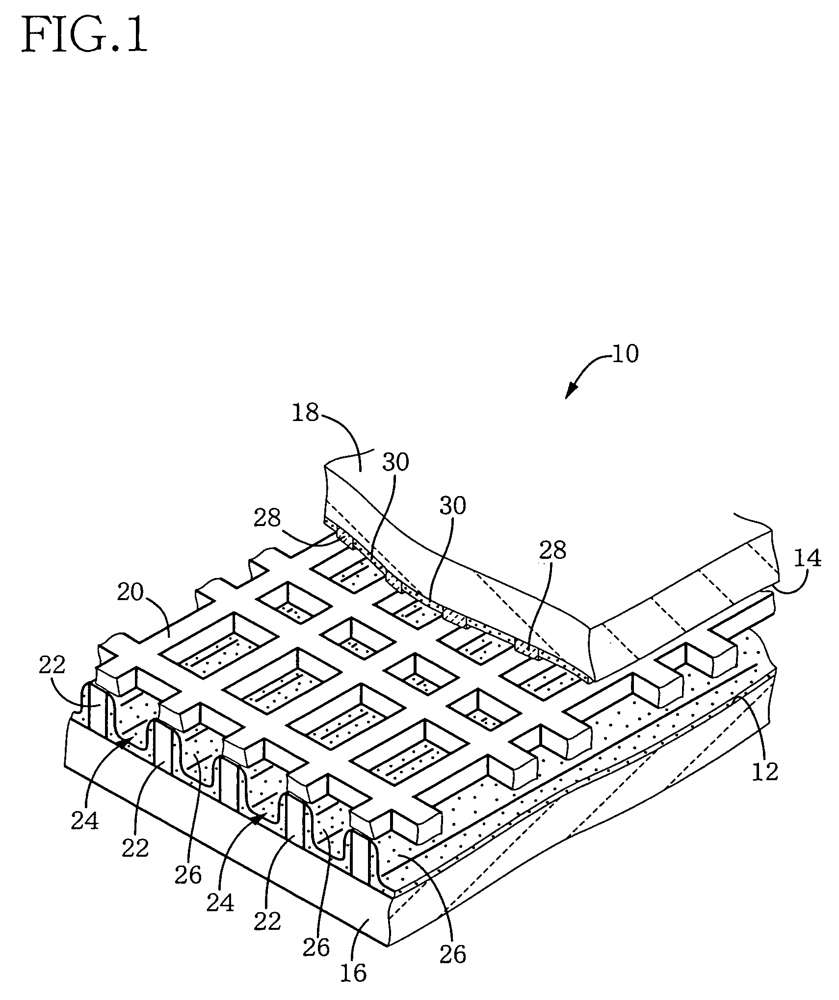
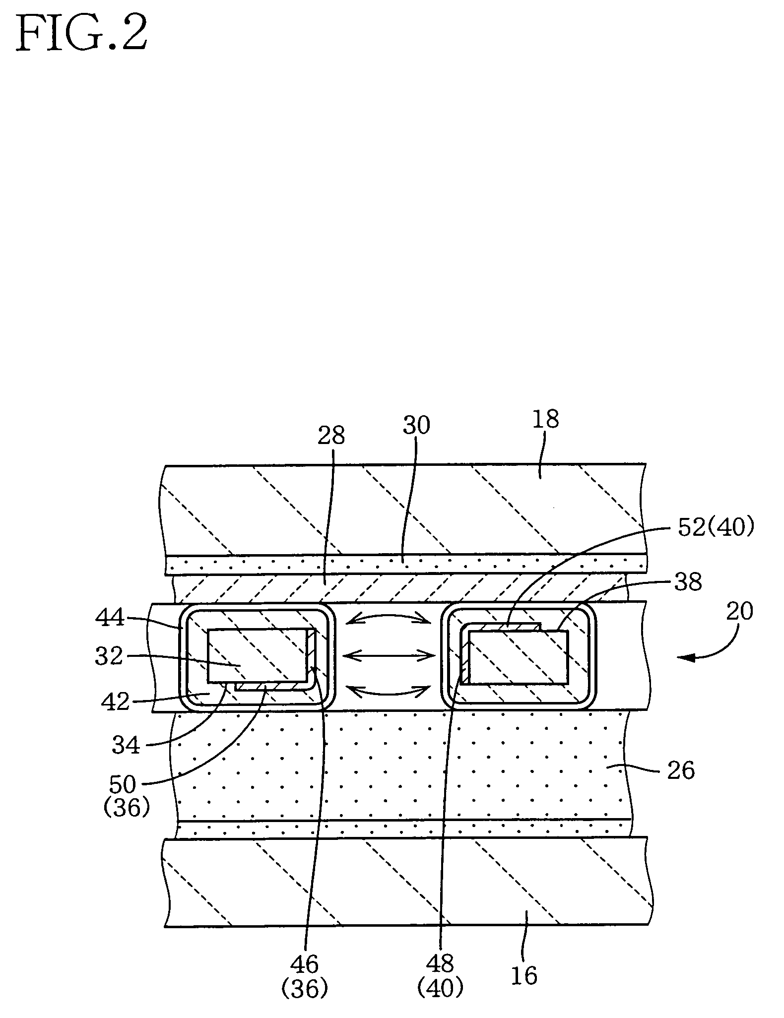
[0142]FIG. 1 is a perspective view for explaining a construction of an AC-type color PDP (hereafter, simply referred to as the PDP) 10 as an example of a gas-discharge display apparatus according to the present invention, such that a portion of the PDP 10 is cut away. In the figure, the PDP 10 includes a front plate 16 and a rear plate 18 which are provided such that the front and rear plates 16, 18 extend parallel to each other and are distant from each other by a pre-determined distance, so that respective one inner surfaces 12, 14 of the front and rear plates 16, 18 which surfaces are substantially flat, oppose each other. A sheet member 20 having a grid pattern is provided between the front and rear plates 16, 18, and peripheral portions of the front and rear plates 16, 18 are gas-tightly sealed. Thus, a gas-tight space is defined in the PDP 10. Each of the front and rear plates 16, 18 has a size of about 900 (mm)× about 500 (mm) and a uniform thickness of from about 1.1 (mm) to...

second embodiment

[0195]FIG. 10 is a perspective view for explaining a construction of an AC-type color PDP (hereafter, simply referred to as the PDP) 210 as an example of a gas-discharge display apparatus according to the third invention, such that a portion of the PDP 210 is cut away. In the figure, the PDP 210 includes a front plate 216 and a rear plate 218 which are provided such that the front and rear plates 216, 218 extend parallel to each other and are distant from each other by a pre-determined distance, so that respective one inner surfaces 212, 214 of the front and rear plates 216, 218 which surfaces are substantially flat, oppose each other. A sheet member 220 having a grid pattern is provided between the front and rear plates 216, 218, and peripheral portions of the front and rear plates 216, 218 are gas-tightly sealed. Thus, a gas-tight space is defined in the PDP 210. Each of the front and rear plates 216, 218 has a size of about 900 (mm)× about 500 (mm) and a uniform thickness of from...

third embodiment

[0242]Next, there will be described another embodiment according to the third and fourth inventions. In the following description, the same reference numerals as used in the above-described embodiment are used to designate the corresponding elements of other embodiments and the description of those elements is omitted.

[0243]FIG. 21 are views corresponding to FIG. 18, for explaining another method of producing the sheet member 220 as described above, that is, a view showing a thick-film paste layer forming step 290, i.e., a step in which the conductive printed layer 302 constituting the sustaining electrodes 248 is formed. In FIG. 21(a), on a film formation surface 278 of a substrate 276 for forming the sheet member 220, there are provided flow stoppers 326 at respective positions inside respective grid bars of the dielectric printed layer 298 (i.e., the dielectric core layer 238) where the sustaining electrodes 248 are to be provided. The flow stoppers 326 are formed of a material c...


PUM


Abstract

When a PDP 10 is produced by superposing, and fixing, a front plate 16 and a rear plate 18 on, and to, each other, a sheet member 20 including an X wiring layer 36 and a Y wiring layer 40 is fixed to the front plate 16 or the rear plate 18, so that X electrodes 46 and Y electrodes 48 are provided in respective discharge spaces 24. Thus, the X electrodes 46 and the Y electrodes 48 can be assembled with the front and rear plates 16, 18, by just placing the sheet member 20 between the two plates 16, 18. Therefore, in the PDP 10, the front plate 16, the rear plate 18, and the discharge electrodes 46, 48 are free of distortions resulting from a heat treatment that would otherwise be carried out to form the electrodes.

Description

TECHNICAL FIELD[0001]The present invention relates to a gas-discharge display apparatus which displays a desired image by utilizing a gas-discharge light emission, and a method of producing a gas-discharge display apparatus.BACKGROUND ART[0002]There is known a gas-discharge display apparatus such as a plasma display panel (PDP) which includes a transparent first substrate (i.e., a front plate), a second substrate (i.e., a rear plate) that is distant from the front plate by a pre-determined distance and extends parallel to the first plate, a plurality of discharge spaces that are provided in a gas-tight space that is located between the front and rear plates and is filled with a pre-selected gas, and a plurality of pairs of first and second discharge electrodes each pair of which selectively produce a gas discharge in a corresponding one of the discharge spaces, and which utilizes the gas discharge to emit a light from a corresponding one of a plurality of light emission units (i.e.,...

Claims


Application Information

Patent Timeline
Patent Type & Authority Patents(United States)
IPC IPC(8): H01J17/49H01J9/02H01J9/24H01J17/04H01J17/16
CPCH01J9/02H01J11/16H01J11/24H01J2211/326H01J2211/245
Inventor SAKAMOTO, SUSUMU
Owner NORITAKE CO LTD
Why Eureka
Try Eureka