Phase lock oscillator and communication equipment

a phase lock and oscillator technology, applied in the direction of pulse automatic control, digital transmission, diversity/multi-antenna systems, etc., can solve the problems of difficult to apply such a structure to terminal equipment of portable type, difficult to realize a frequency synthesizer with a broad band, and severe demands for cost reduction, downsizing, and lightening. achieve the effect of high stability, wide capture range and high transmission quality

Inactive Publication Date: 2006-06-27
FUJITSU LTD
View PDF12 Cites 10 Cited by
  • Summary
  • Abstract
  • Description
  • Claims
  • Application Information

AI Technical Summary

Benefits of technology

[0029]It is an object of the present invention to provide: a phase lock oscillator which is suitable for integration and has a wide capture range and a lock range in order to flexibly adapt to variances in environmental condition; and a communication equipment in which transmission quality and service quality are highly maintained with stability by incorporating a frequency synthesizer.
[0030]It is another object of the present invention to greatly reduce limitations to achieving integration of an equipment which can realize cost reduction, downsizing, and reduction in power consumption, and to improve service quality and reliability without any basic changes in configuration, in a transmission system to which the invention is applied.
[0031]It is still another object of the present invention to broaden the bands of the capture range and the lock range even when the lock range may possibly fluctuate due to a change in environmental conditions and so on.

Problems solved by technology

Therefore, it has been difficult to realize a frequency synthesizer with a broad band unless a control system in which the complication of a hardware structure thereof is tolerated and the partial bands can be switched at a high rate is applied thereto.
However, in general, it is difficult to apply such a structure to terminal equipment of a portable type in which cost reduction, downsizing, and lightening are severely demanded as well as reduction in power consumption.
Furthermore, in recent years, the integration of a radio part which is to be mounted in terminal equipment of a portable type is strongly demanded with the aim of realizing the above demands, and as a result, the variable range of the capacitance of the variable-capacitance diode 81 and a feasible value of the quality factor Q of the inductor 85 are actually limited to small values as well.
Therefore, the lock state mentioned above is not always maintained when temperature, a power-supply voltage, and other environment conditions change, which may possibly lower service quality and transmission quality since the maintenance of a radio transmission channel is prevented.
Consequently, it has been difficult to actually employ the configuration in which the self-tuning is repeatedly retried at a predetermined frequency.

Method used


Image

  • Phase lock oscillator and communication equipment
  • Phase lock oscillator and communication equipment
  • Phase lock oscillator and communication equipment

Examples


first embodiment

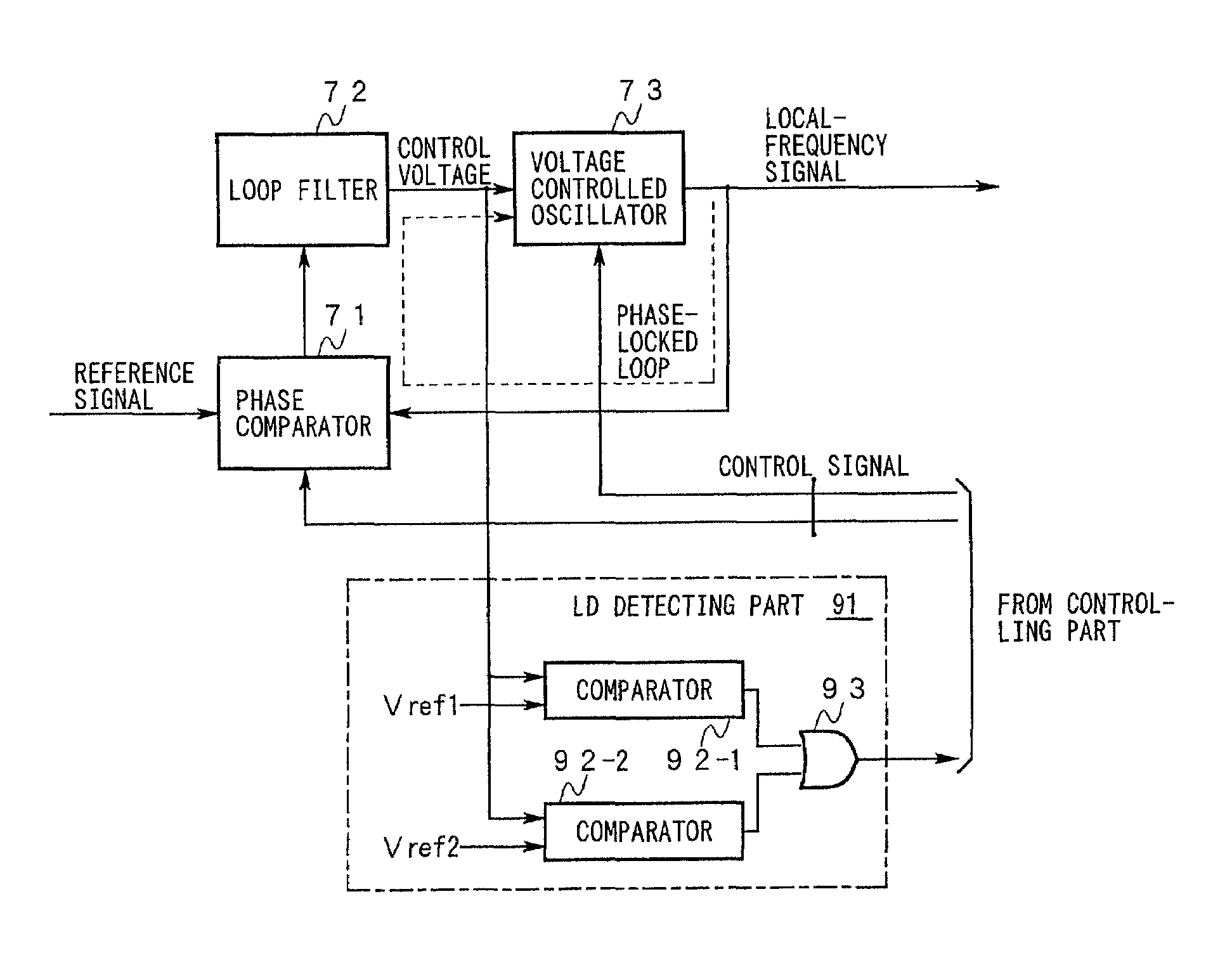
[0139]FIG. 4 is a diagram showing the present invention.

[0140]In the drawing, the same symbols and numerals are used to designate the same components as those in FIG. 11 and the explanation thereof is omitted here.

[0141]A main different point of this invention from a conventional example shown in FIG. 11 is that an output of a loop filter 72 is connected to a corresponding input of a controlling part via an LD detecting part 91.

[0142]The LD detecting part 91 is composed of the following components:[0143]a comparator 92-1 where one input thereof is given a reference voltage Vref1 and another input thereof is connected to the output of the loop filter 72;[0144]a comparator 92-2 where one input thereof is given a reference voltage Vref2 and another input is connected to the output of the loop filter 72; and[0145]an OR gate 93 having two inputs individually connected to outputs of the comparators 92-1, 92-2 and being disposed as a final stage of the LD detecting part 91.

[0146]FIG. 5 is ...

third embodiment

[0159]FIG. 7 is a diagram showing a second and the present invention.

[0160]In the drawing, the same symbols and numerals are used to designate the same components as those in FIG. 4 and the explanation thereof is omitted here.

[0161]This embodiment is composed of the following components:[0162]an antenna 51;[0163]an antenna duplexer (DUP) 52 with an antenna terminal thereof connected to a feeding point of the antenna 51;[0164]a receiving part 53 with an input thereof connected to a reception output of the antenna duplexer 52;[0165]a transmitting part 54 with an output thereof connected to a transmission input of the antenna duplexer 52;[0166]a first local oscillation part 55 having an output thereof connected to first local frequency inputs of the receiving part 53 and the transmitting part 54 and having basically the same structure as that of the frequency synthesizer shown in FIG. 4;[0167]a second local oscillation part 56 having an output thereof connected to second local frequenc...

second embodiment

[0173]FIG. 8 is a time chart showing an operation in the second embodiment according to the present invention.

[0174]The operation in the second embodiment according to the present invention is explained below with reference to FIG. 7 to FIG. 9 and FIG. 4.

[0175]A basic operation of each part is explained first.

[0176]The controlling part 61 executes programs accumulated in advance in a memory, which is not shown, to control processing relating to channel control and man-machine interface, and initializes, at the start, the reference signal generating part 58, the receiving power source part 59, and the transmitting power source part 69 together with the local-frequency controlling part 57.

[0177]The reference signal generating part 58 constantly generates a reference signal with a frequency designated by the controlling part 61 at the time of the initialization and supplies the reference signal to the first local oscillation part 55 and the second local oscillation part 56.

[0178]The lo...


PUM


Abstract

The present invention relates to a phase lock oscillator which has a phase-locked loop including a reactive element and varies a reactance of the reactive element at an instant prior to an instant at which the phase-locked loop reaches a limit of maintaining its lock state, and relates to a communication equipment with the lock phase oscillator mounted therein. The phase lock oscillator and the communication equipment can flexibly adapt to variances in environment conditions and maintain stable and high service quality.

Description

BACKGROUND OF THE INVENTION[0001]1. Field of the Invention[0002]The present invention relates to a phase lock oscillator comprising a voltage controlled oscillator whose oscillation frequency changes according to a control voltage and a communication equipment with the phase lock oscillator mounted therein.[0003]2. Description of the Related Art[0004]There have been seriously demanded downsizing, lightening, and reduction in power consumption for terminal equipment of a portable type which can provide a communication service to subscribers of a mobile communication system, so that the terminal equipment incorporates a frequency synthesizer which can realize a smooth access to a desired radio channel in a process of channel control performed in cooperation with a radio base station.[0005]FIG. 11 is a diagram showing a structural example of a conventional frequency synthesizer.[0006]In the drawing, a first input of a phase comparator 71 is given a reference signal with a known frequen...

Claims


Application Information

Patent Timeline
Patent Type & Authority Patents(United States)
IPC IPC(8): H03L7/095H03L7/099H03L7/10H04B1/04H04B1/26H04B1/3822H04B1/40H04L7/033
CPCH03L7/10H03L7/099H03L7/102
Inventor YONEKURA, KUNITOSHI
Owner FUJITSU LTD
Why Eureka
Try Eureka