Motion detection imaging device

a technology for motion detection and imaging devices, which is applied in the field of motion detection imaging devices, can solve the problems of not developing an imaging device for motion detection, the image captured by the optical lens to have barrel distortion, and the use of complex programs to digitally correct the barrel distortion, etc., to prevent the probability of detecting a target object from being lowered, and the capture range is larg

Inactive Publication Date: 2009-11-17
FUNAI ELECTRIC CO LTD
View PDF15 Cites 0 Cited by
  • Summary
  • Abstract
  • Description
  • Claims
  • Application Information

AI Technical Summary

Benefits of technology

[0007]An object of the present invention is to provide a motion detection imaging device which is capable of imaging in a wide capture range with as simple an optical system as possible without using an optical lens having a view angle much greater than 60°, and which can easily, and at short intervals, capture multiple images for motion detection, thereby preventing lowering of the probability of detecting a target object even when the target moves at a high speed.
[0016]The motion detection imaging device according to each of the first and second aspects of the present invention uses an optical lens system comprising: an optical lens array having center lenses for collecting light entering in a front range of a capture range, and also having left and right side lenses for collecting lights entering in left and right ranges of the capture range; and light bending means (prisms or mirrors) for guiding the lights entering in the left and right ranges of the capture range to the left and right side lenses. Thus, the motion detection imaging device can capture an image in a wide capture range with a simple optical system without using an optical lens having a view angle much larger than approximately 60°.
[0017]In addition, the motion detection imaging device further comprises: rolling shutter means for allowing the solid-state imaging element to image single-eye images with a time difference between the single-eye images in adjacent rows of the single-eye images; image combining means for combining the single-eye images in each of the rows of single-eye images so as to reproduce a wide angle image, thereby reproducing multiple wide angle images with a time difference between the wide angle images in adjacent rows; and motion detection means for detecting a target object in the wide angle images based on a difference between the wide angle images. Thus, the motion detection imaging device can easily, and at short intervals, capture multiple images for motion detection by one operation of a shutter, making it possible to detect, with high detection probability (preventing lowering of the probability), a target object moving at a high speed.

Problems solved by technology

Generally, an optical lens having a view angle much greater than 60°, as can be represented by a fisheye lens, causes a resultant image captured by the optical lens to have barrel distortion.
This requires the use of complex programs to digitally correct the barrel distortion.
In other words, there has not been developed an imaging device for motion detection which is capable of capturing or imaging a wide range with a simple structure.
However, in the case where the predetermined intervals of the shutter are long (frame rate is low), a problem arises that it is highly unlikely to detect motion of a target object moving at a high speed such as a moving car.

Method used


Image

  • Motion detection imaging device
  • Motion detection imaging device
  • Motion detection imaging device

Examples


first embodiment

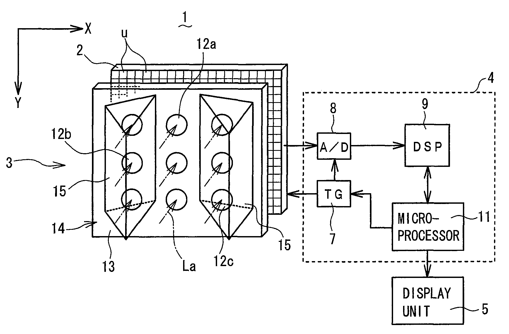
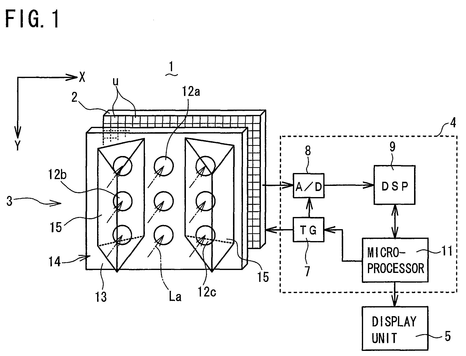
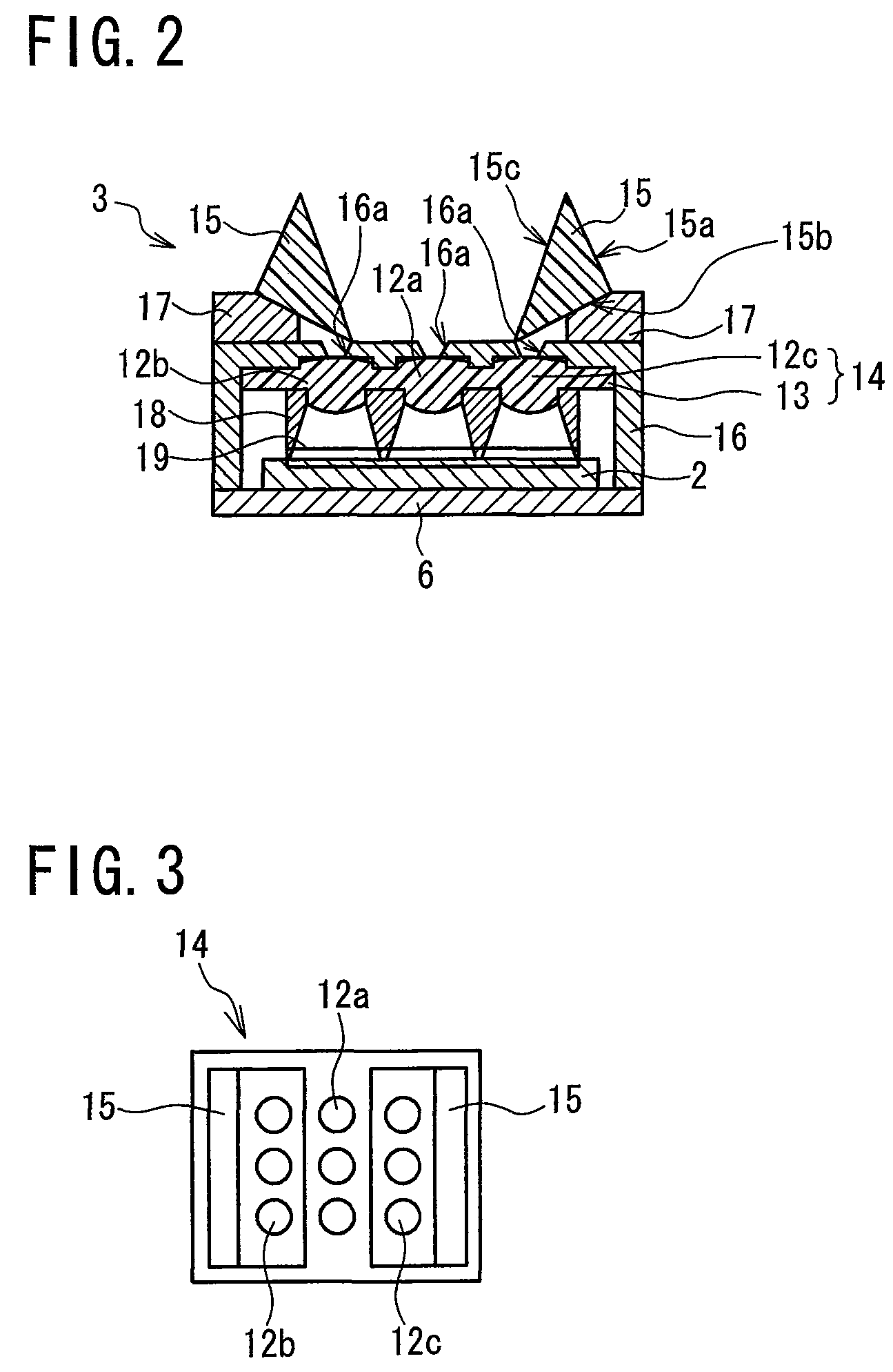
[0032]Referring to FIG. 1 to FIG. 8, a motion detection imaging device (imaging device for motion detection) 1 according to a first embodiment of the present invention will be described. FIG. 1 is a schematic perspective view of the motion detection imaging device 1 including a solid-state imaging element 2 and an optical lens system 3, while FIG. 2 is a schematic bottom cross-sectional view of the motion detection imaging device 1 of FIG. 1. As shown in FIG. 1, the motion detection imaging device 1 comprises: a solid-state imaging element (photodetector array) 2 having unit pixels “u” arranged in a matrix of rows and columns (X and Y directions); and an optical lens system 3 for collecting light entering in a front capture range (picture-taking range) of 120° so as to form images on the solid-state imaging element 2. The motion detection imaging device 1 further comprises: a motion detection circuit 4 for reading the formed images on the solid-state imaging element 2 as image infor...

second embodiment

[0057]Referring to FIG. 9, a motion detection device 1 according to a second embodiment of the present invention will be described. The motion detection device 1 of the second embodiment is similar to that of the first embodiment, except that 30-60-90 degree right-angle prisms 215 (claimed “light bending means”) are placed on the entrance side of the optical lens array 14 here in place of the 45-45-90 degree right-angle prisms 15 used in the first embodiment. FIG. 9 is a schematic optical path diagram of an optical lens system 203 of the motion detection device 1 according to the second embodiment as seen from the bottom thereof, showing a light flux passing through each of the optical lenses 12a, 12b, 12c. Similarly as in the first embodiment, the optical lens system 203 has an optical lens array 14 of optical lenses 12a, 12b, 12c and a solid-state imaging element 2. Thus, description of parts similar to those in the first embodiment is omitted where appropriate.

[0058]As shown in F...

third embodiment

[0062]Referring next to FIG. 10, a motion detection device 1 according to a third embodiment of the present invention will be described. The motion detection device 1 of the third embodiment is similar to that of the first embodiment, except that the nine optical lenses 12a, 12b, 12c have a capture range of 60° or approximately 60° (which importantly is not larger than approximately 60°) to expand the capture range of the optical lens system 3 of the first embodiment to approximately 180°, and that equilateral triangle prisms 315 (claimed “light bending means”) for guiding light are placed on the light entrance side of an optical lens array 14 in place of the 45-45-90 degree right-angle prisms 15 of the first embodiment. FIG. 10 is a schematic optical path diagram of an optical lens system 303 of the motion detection imaging device 1 according to the third embodiment as seen from the bottom thereof, showing a light flux passing through each of the optical lenses 12a, 12b, 12c. Simil...


PUM


Abstract

A motion detection imaging device comprises an imaging element and an optical lens system for collecting light entering in a capture range to form images on the imaging element. The optical lens system comprises: an optical lens array having center lenses for collecting light in a front capture range and left / right side lenses for collecting lights in side capture ranges; and prisms for guiding lights in the side capture ranges to the side lenses. The imaging device further comprises: a timing generator for allowing images formed by the lenses to be imaged with a time difference between in-row images; and a microprocessor for reproducing wide angle images from the in-row images by one operation of a shutter to detect movement of a target based on difference between the wide angle images. The imaging device with simple structure can monitor, with high probability, a target moving fast in a wide range.

Description

BACKGROUND OF THE INVENTION[0001]1. Field of the Invention[0002]The present invention relates to a motion detection imaging device.[0003]2. Description of the Related Art[0004]A motion detection imaging device is known which calculates a difference between images captured with a time difference on a solid-state imaging element, and detects movement or motion of a target object (to be captured or imaged) based on the calculated difference (refer to e.g. Japanese Laid-open Patent Publication 2003-32552). It is also know to detect a moving object based on a difference between digitized images (refer to e.g. Japanese Laid-open Patent Publications 2001-177836, 2004-171431 and Hei 8-106534). On the other hand, an electronic still camera is known which uses an image sensor with a light receiving surface having divided light receiving areas, and sequentially exposes images of a target object on the light receiving areas so as to allow images in the light receiving areas to be read out all t...

Claims


Application Information

Patent Timeline
Patent Type & Authority Patents(United States)
IPC IPC(8): H04N5/228G06K9/00H01L27/00H04N5/235H04N5/225G02B5/04
CPCH04N5/3415H04N5/23238H04N5/3532H04N23/698H04N25/41H04N25/531
Inventor NAKAO, YOSHIZUMITOYODA, TAKASHIMASAKI, YASUO
Owner FUNAI ELECTRIC CO LTD
Why Eureka
Try Eureka