Sequence circuit display method of injection molding machine

Inactive Publication Date: 2006-06-27
MEIKI
View PDF5 Cites 1 Cited by
  • Summary
  • Abstract
  • Description
  • Claims
  • Application Information

AI Technical Summary

Benefits of technology

[0006]An object of the present invention is to provide a sequence circuit display method for an injection molding machine which enables a sequence circuit corresponding to an operating step to be quickly

Problems solved by technology

It did not enable an individual grasp of the connectio

Method used


Image

  • Sequence circuit display method of injection molding machine
  • Sequence circuit display method of injection molding machine
  • Sequence circuit display method of injection molding machine

Examples


Example

[0017]Preferred embodiments of the present invention will be described in detail below while referring to the attached figures.

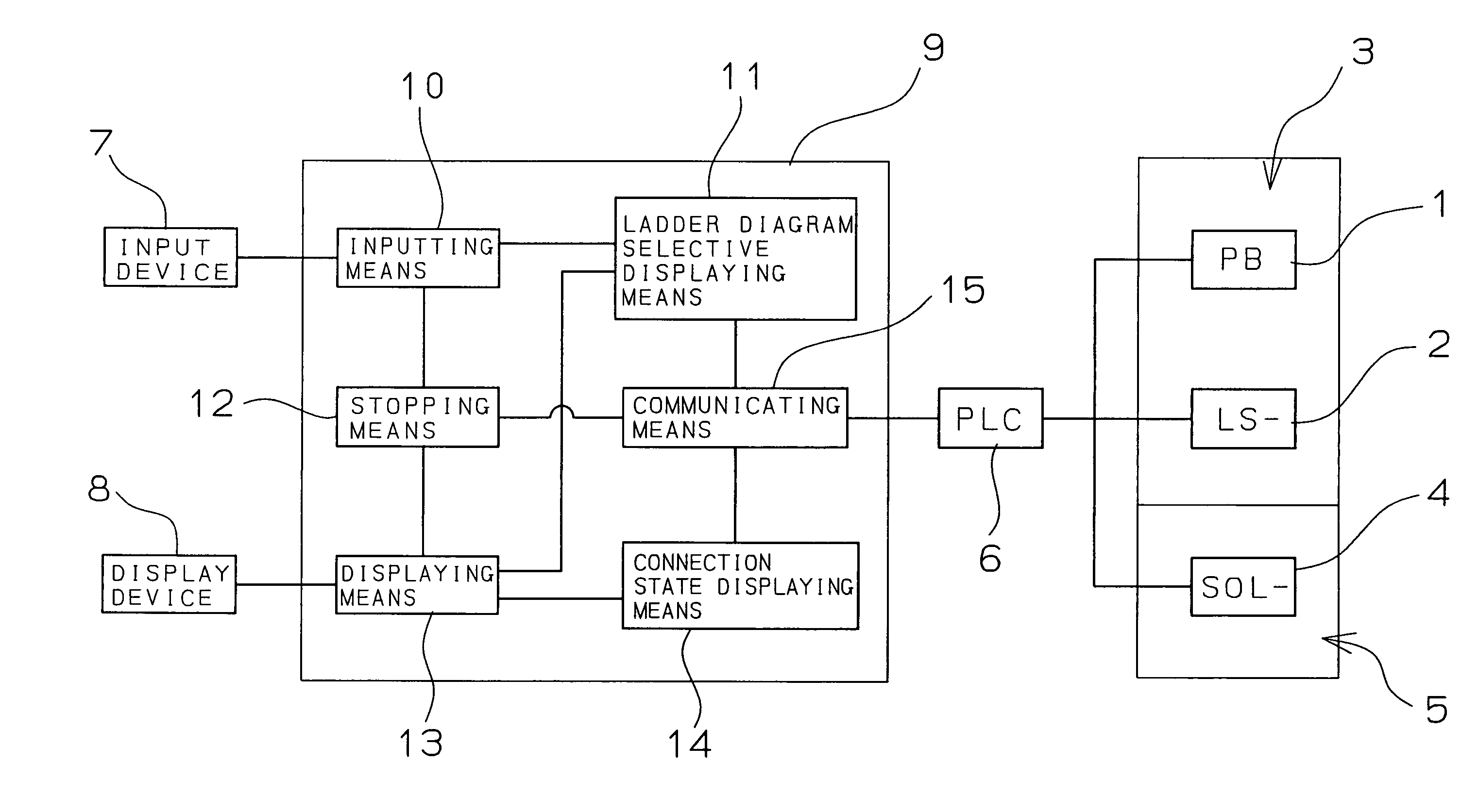
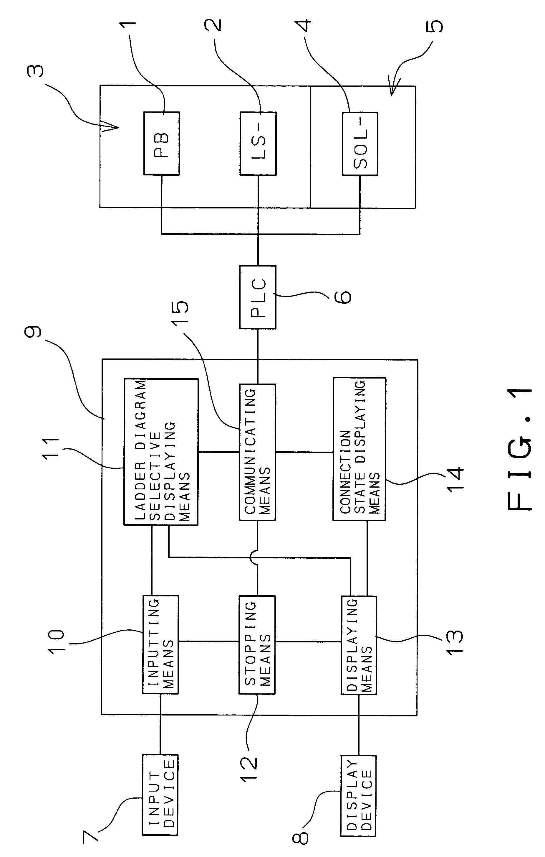
[0018]First, a block diagram of a sequence circuit display device of an injection molding machine of an embodiment of the present invention will be explained with reference to FIG. 1. The injection molding machine is provided with an input device 3 comprised of pushbutton switches 1 for inputting various types of molding conditions etc., limit switches 2 for turning on / off operation in accordance with the operation of the injection molding machine, and other sensors and an output device 5 comprised of solenoid valves 4 etc. for driving the injection molding machine. In a power servo type injection molding machine, the output device 5 is constituted by a servo amplifier, servo motor, etc.

[0019]The input device 3 and output device 5 are connected to a programmable logic controller (PLC) 6. The PCL 6 is a sequential controller which receives as input the signal...


PUM


Abstract

A sequence circuit display method for an injection molding machine which enables a sequence circuit corresponding to an operating step to be quickly displayed and enables the connection states of contacts, coils, etc. in a sequence circuit to be easily grasped when obtaining a grasp of the sequence circuit, comprising selectively inputting an operating step name in an injection molding machine from an input device to thereby display a sequence circuit including contacts, coils, etc. corresponding to the selected input operating step as a ladder diagram on a display device; comprising displaying a sequence circuit of an injection molding machine as a ladder diagram on a display device and selectively inputting one of the contacts, coils, etc. in the ladder diagram to thereby display a sequence circuit including contacts, coils, etc. corresponding to the selected input contact, coil, etc. as a ladder diagram on the display device; etc.

Description

BACKGROUND OF THE INVENTION[0001]1. Field of the Invention[0002]The present invention relates to a sequence circuit display method for an injection molding machine displaying a sequence circuit in an injection molding machine used for molding a plastic material, metal material, etc. as a ladder diagram on a display device. More particularly, it relates to a sequence circuit display method for an injection molding machine displaying a sequence circuit including a contact, coil, etc. corresponding to a selectively input operating step name as a ladder diagram on a display device.[0003]2. Description of the Related Art[0004]As a method for displaying a sequence in an injection molding machine on a display screen, there is the one described in Japanese Patent Publication (A) No. 6-91716. Japanese Patent Publication (A) No. 6-91716 displays a graphic of the injection molding machine on a displaying means of the injection molding machine and moves that graphic to show the operation being ...

Claims


Application Information

Patent Timeline
IPC IPC(8): G06F19/00B29C45/76G05B11/01G05B19/048G05B19/05G05B19/409
CPCB29C45/76G05B19/409B29C2045/7606B29C2945/76551G05B2219/35505G05B2219/13047G05B2219/13052B29C2945/76993
Inventor TANIZAWA, SEIJIOSAWA, KAZUYUKIOKADO, SHOJI
Owner MEIKI
Why Eureka
Try Eureka