Time measurement device and method of controlling the time measurement device

Active Publication Date: 2006-07-18
SEIKO EPSON CORP
View PDF19 Cites 24 Cited by
  • Summary
  • Abstract
  • Description
  • Claims
  • Application Information

AI Technical Summary

Benefits of technology

[0017]It is an object of the present invention to overcome the drawback of the conventional art, and to provide a time measurement device and a method of controlling the time me

Problems solved by technology

There may be a case where the receiving means fails to receive the time information when the watch returns to the standard mode from the power saving mode.
For example, if the radio wave corrected watch is in a building, the long-wave time standard radio wave may be blocked by the building walls and may fail to

Method used


Image

  • Time measurement device and method of controlling the time measurement device
  • Time measurement device and method of controlling the time measurement device
  • Time measurement device and method of controlling the time measurement device

Examples


first embodiment

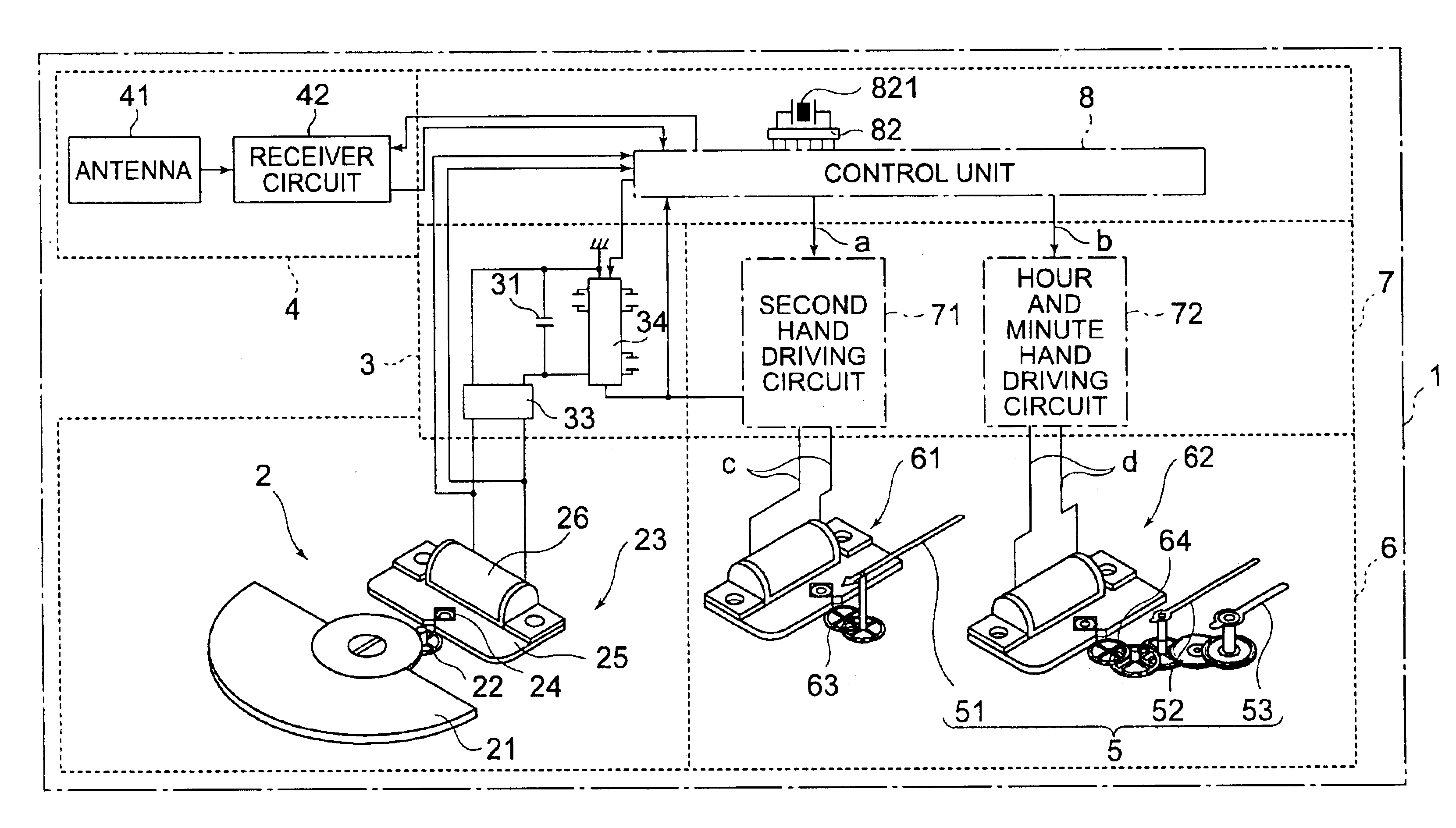
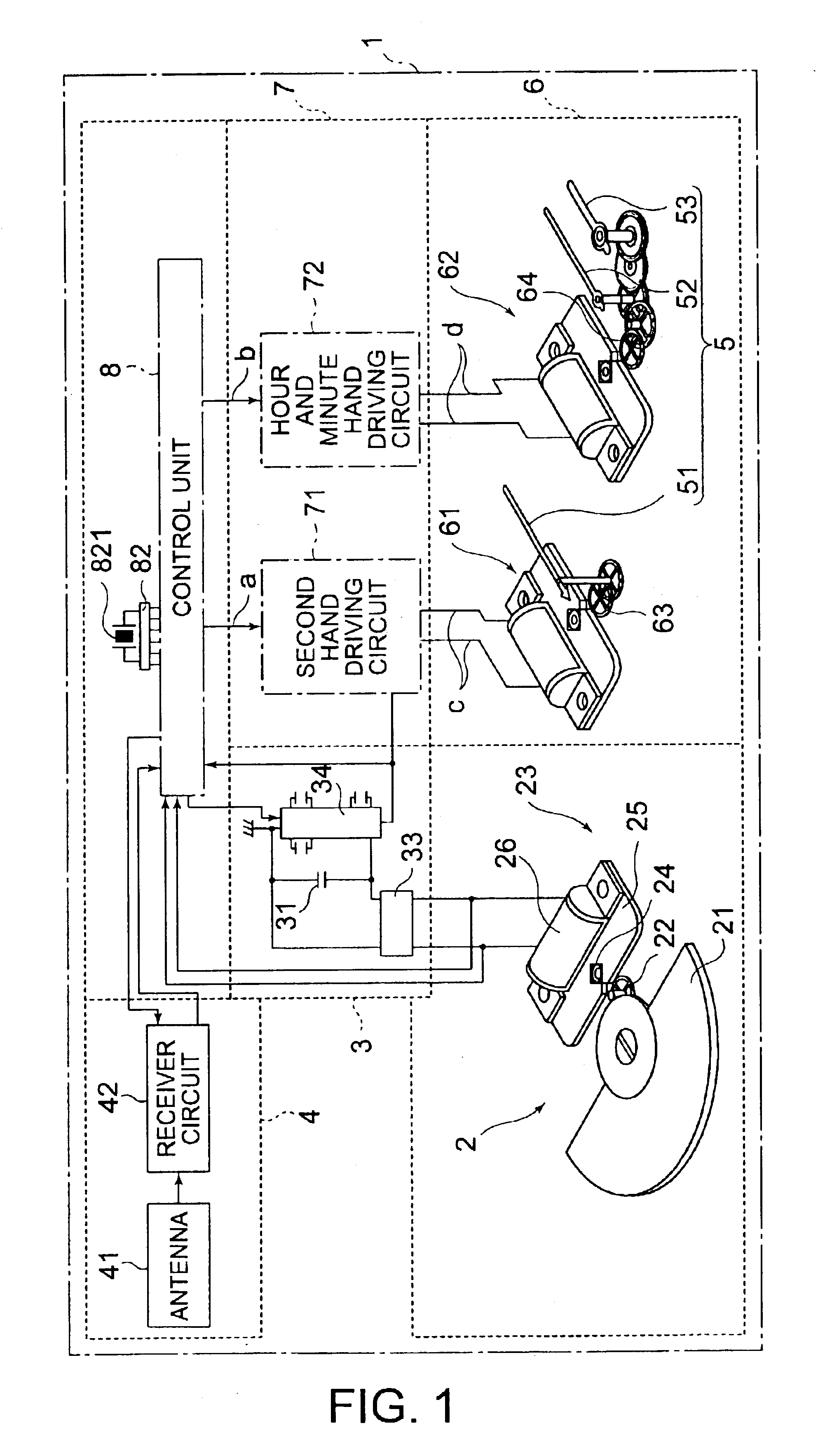
[0073]FIG. 1 shows a radio wave corrected wrist watch of as a first embodiment of a time measurement device of the present invention.

[0074]A radio wave corrected watch 1 includes a power generator 2 as power generating means, a power storage unit 3 for storing power generated by the power generator 2, a receiver 4 for receiving a radio wave bearing time information, a control unit 8 for controlling the driving of the entire device, a hand advancing unit 6 for advancing time-indicating hands as a time display means for indicating the time, and a driving circuit section 7 for driving the hand advancing unit 6 in response to a drive control signal from the control unit 8. These components are housed in a device case (not shown). Belts (not shown) are connected to the device case to allow a user to wear the radio wave corrected watch 1 on the user's wrist.

[0075]The power generator 2 includes a semi-circular disk-like rotating weight 21 rotatably supported at the center thereof, a transf...

second embodiment

[0141]A second embodiment of the present invention will now be discussed. The basic structure of the second embodiment is the same as that of the first embodiment, and the feature of the second embodiment lies in the operation thereof performed when the power saving mode reverts to the standard mode.

[0142]FIG. 7 shows a flow diagram of the second embodiment when the device reverts to the standard mode from the power saving mode.

[0143]The second embodiment remains unchanged from the first embodiment in the two steps, in which, when the user wears the radio wave corrected watch 1 on the wrist again for use out of the power saving mode, the generated power detector circuit 84 detects whether the power generator 2 generates power (ST31), and the voltage detector circuit 85 detects whether the magnitude of the storage voltage VSS in the secondary power source 31 is equal to or greater the standard voltage value VL (ST34).

[0144]When it is determined that the magnitude of the storage volta...

third embodiment

[0153]FIG. 8 illustrates a third embodiment of the present invention. The third embodiment is basically identical to the first and second embodiments in structure, and the third embodiment has the following features.

[0154]The third embodiment has a solar cell 27 as a power source. The third embodiment includes a carried-state detector circuit 94 as carried-state detecting means instead of the generated power detector circuit 84 used in both the first and second embodiments. The carried-state detector circuit 94 may employ an acceleration sensor which detects acceleration taking place when the user wears the radio wave corrected watch 1 on the wrist.

[0155]When the user uses the radio wave corrected watch 1 mounted on the wrist, the carried-state detector circuit 94 can detect a motion generated in the radio wave corrected watch 1 (a carried-state detecting step). When a carried-state is detected, the carried-state detector circuit 94 outputs a carried-state detection signal q to the ...


PUM


Abstract

A time measurement device includes a power generator 2, secondary power source 31, current time counters 922 and 932, receiver circuit 42 for receiving a time standard radio wave, time display means 5 for displaying the current time, power detector 83 for outputting a power detection signal when the power generator 2 is in a power generating state or when a voltage stored in the secondary power source 31 is at a predetermined voltage value, operation mode switcher 874 switching, in response to the power detection signal, between a power saving mode in which time display is suspended and a standard mode in which time display is not suspended. The operation mode switcher 874 causes the time display means 5 to display the current time based on the time information counted by the time counters 922 and 932 and the time information received by the receiver circuit in response to the device being switched from the power saving mode to the standard mode.

Description

BACKGROUND OF THE INVENTION[0001]1. Field of the Invention[0002]The present invention relates to a time measurement device and a method for controlling the time measurement device. Particularly, the present invention relates to a time measurement device having a function of power saving and a function of receiving a radio wave bearing time information, and a method for controlling the time measurement device.[0003]2. Description of the Related Art[0004]A radio wave corrected watch having a power saving function is known as a time measurement device which has the function of saving power and the function of receiving a radio wave bearing time information. Japanese Unexamined Patent Application Publication No.11-223684 discloses such a radio wave corrected watch.[0005]The radio wave corrected watch includes a current time counter for counting current time, time display means for displaying current time of the current time counter, receiving means for receiving a radio wave bearing tim...

Claims


Application Information

Patent Timeline
IPC IPC(8): G04C11/02G04C10/04G04G5/00G04G19/00G04G19/12G04G21/04G04G99/00G04R20/08G04R60/14
CPCG04G19/12G04R20/08G04G21/04G04G99/00
Inventor OKEYA, MAKOTO
Owner SEIKO EPSON CORP
Why Eureka
Try Eureka