Magnetic field analysis method and programs for rotating machines

a magnetic field and analysis method technology, applied in the direction of electric/magnetic computing, analogue processes for specific applications, instruments, etc., can solve the problems of large calculation time and ineffective methods, and achieve the effect of shortening the calculation tim

Inactive Publication Date: 2006-06-27
HITACHI LTD
View PDF17 Cites 4 Cited by
  • Summary
  • Abstract
  • Description
  • Claims
  • Application Information

AI Technical Summary

Benefits of technology

[0006]An object of this invention is to provide a rotating machine magnetic field analysis method and its program capable of shortening a calculation time.

Problems solved by technology

This method becomes ineffective when the rotation angle width exceeds a certain value.
This requires, however, a large number of iterations necessary for obtaining a solution, taking a large calculation time.

Method used


Image

  • Magnetic field analysis method and programs for rotating machines
  • Magnetic field analysis method and programs for rotating machines
  • Magnetic field analysis method and programs for rotating machines

Examples


Embodiment Construction

[0018]Embodiments of a magnetic field analyzing method of this invention will be described with reference to the accompanying drawings.

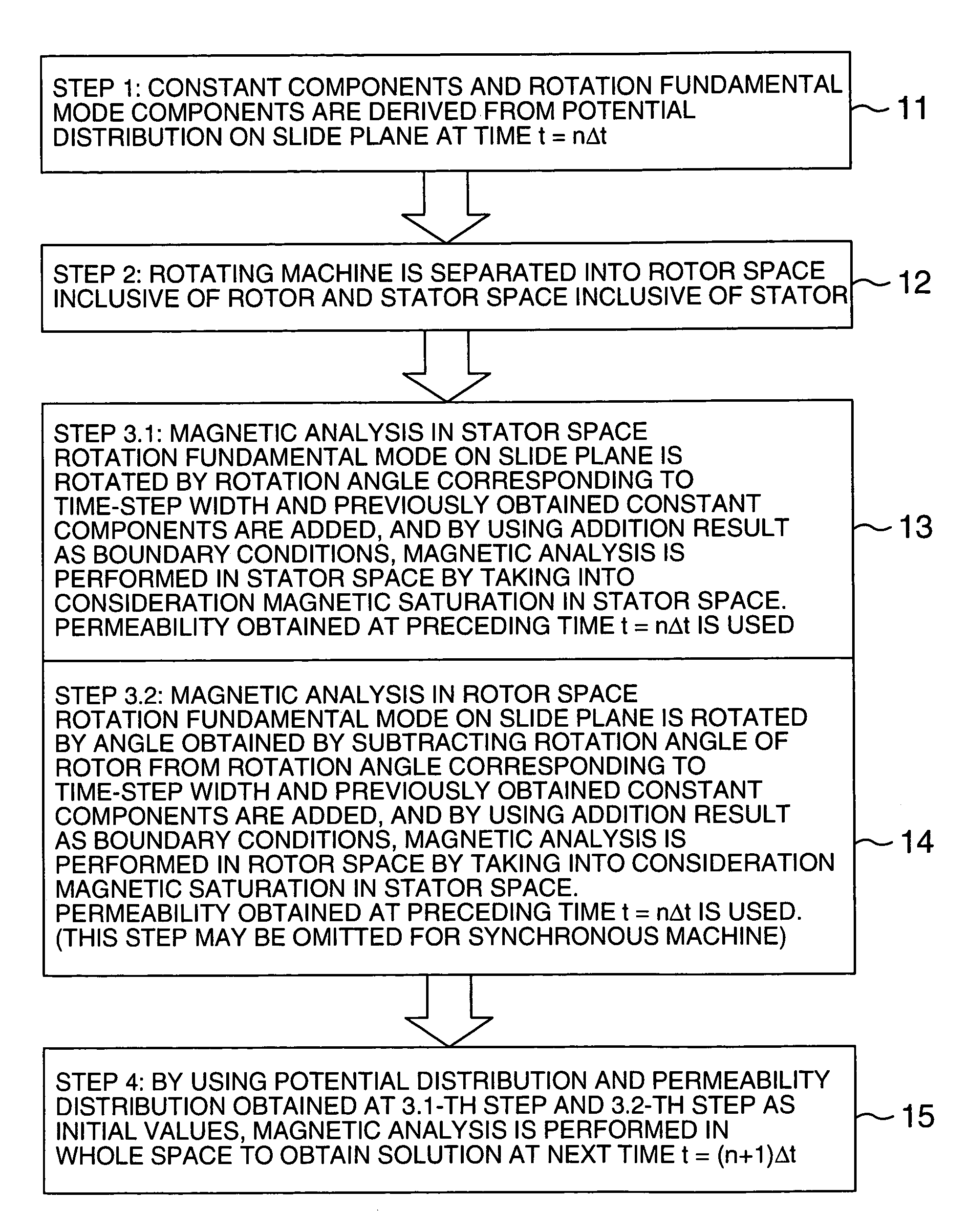
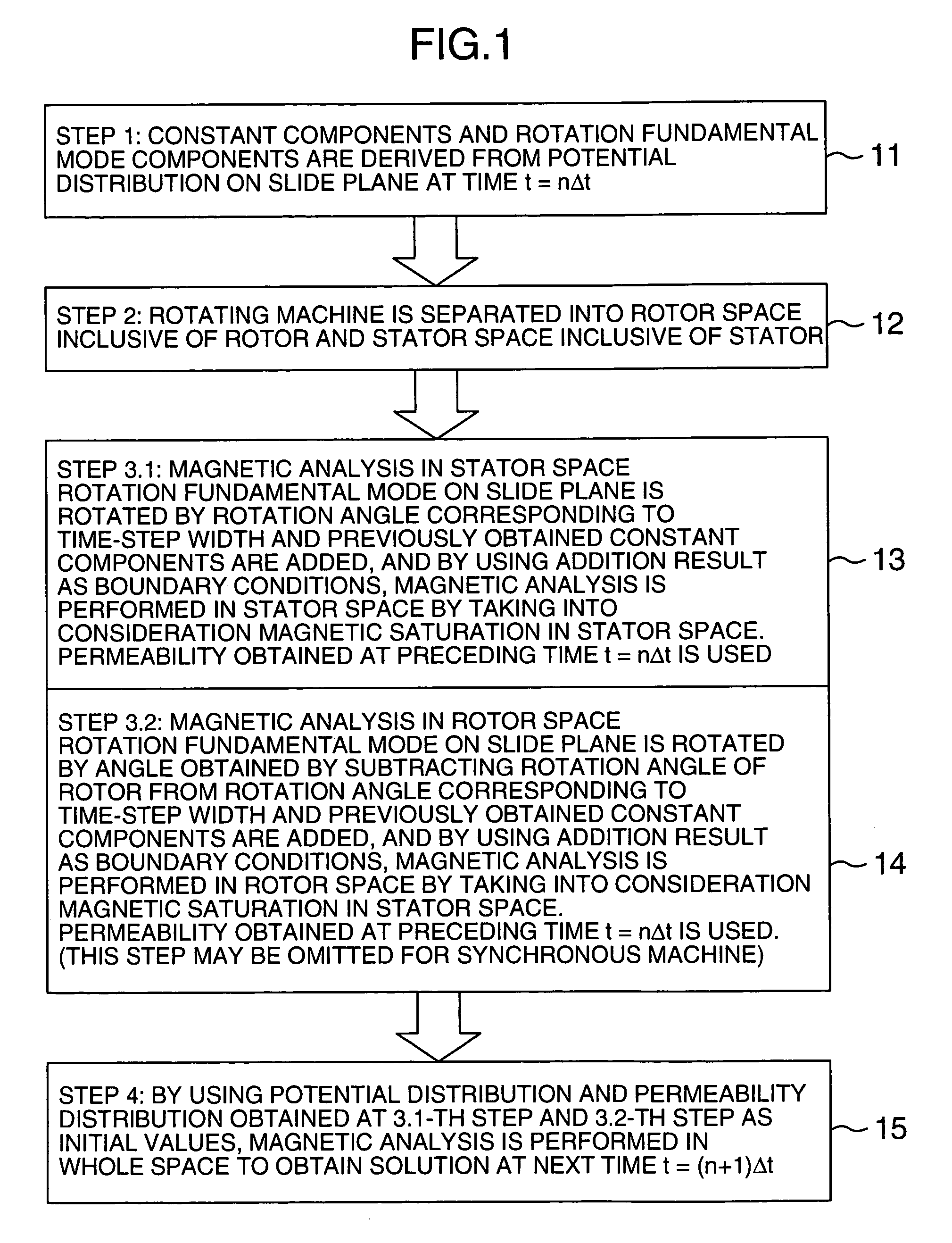
[0019]FIG. 1 illustrates an example of a flow of a magnetic field analysis method according to a first embodiment of the invention. Since a magnetic field distribution is analyzed generally by utilizing a potential, the embodiments will be described also by utilizing a potential.

[0020]At the first step 11, a potential on a slide plane between the rotor and stator is calculated from a potential distribution at a predetermined time, e.g., n-th time t=nΔt where Δt is a time-step width. This solution is separated into each mode along a rotation direction to derive constant components and rotation fundamental mode components.

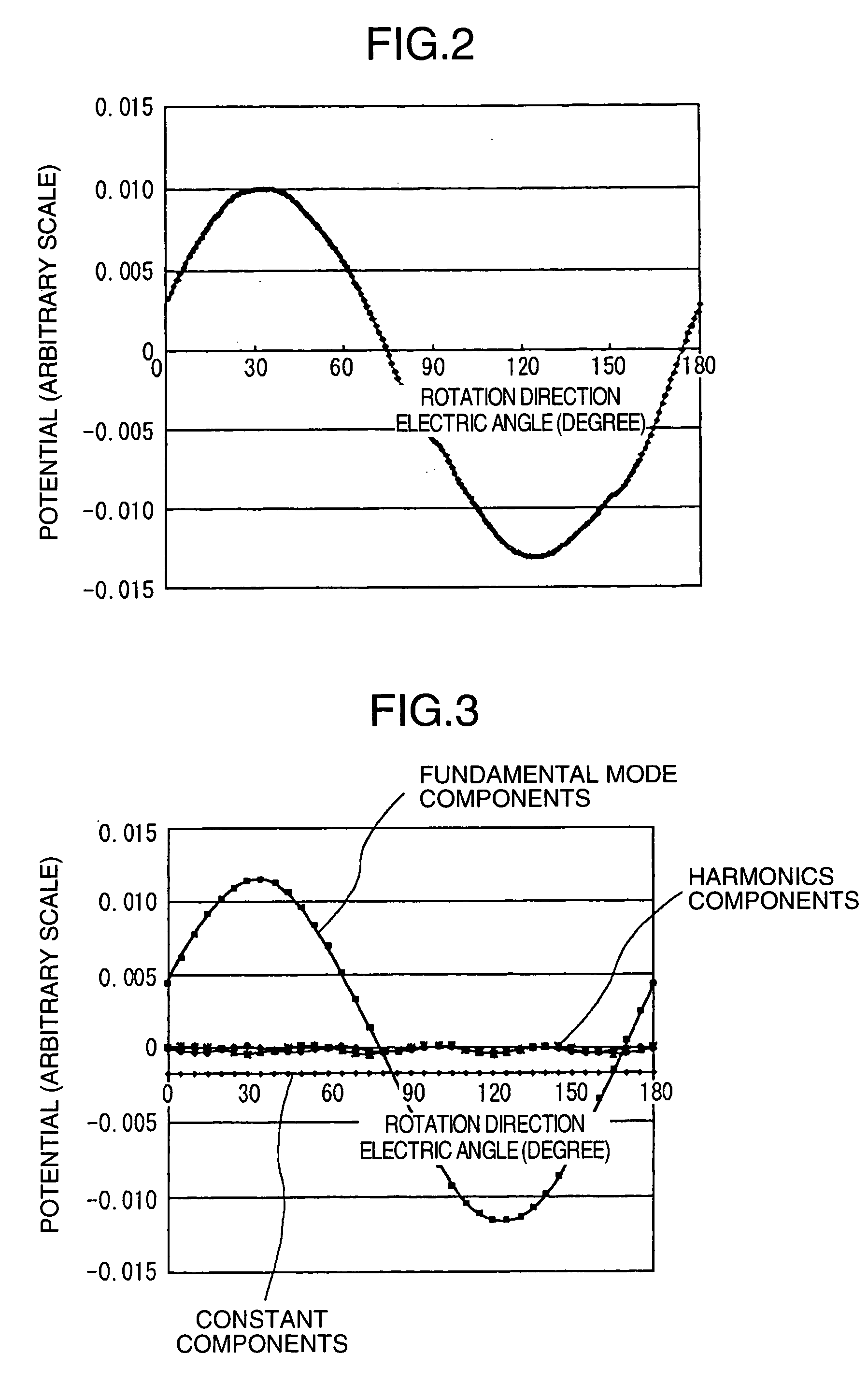
[0021]FIG. 2 shows an example of a potential distribution on the slide plane, and FIG. 3 is a graph showing the potential distribution separated into each mode. As shown in FIG. 3, the potential solution on the slide plane can be reso...


PUM

PropertyMeasurementUnit
magnetic field analysisaaaaaaaaaa
magnetic field distributionaaaaaaaaaa
magnetic fieldaaaaaaaaaa

Abstract

Constant components and rotation fundamental mode components on the slide plane between a rotor and a stator are derived from a magnetic field distribution at a predetermined time. The analysis space is divided into a rotor space and a stator space. A fundamental mode on the slide plane is rotated by a rotation angle of a rotation magnetic field corresponding to a time-step width. A solution obtained in this state is added to the constant components. By using the addition result as the boundary conditions on the slide plane, non-linear magnetic field analysis is performed by taking into consideration the magnetic saturation in the stator space. The rotation fundamental mode on the slide mode is rotated by an angle obtained by subtracting the rotation angle of the rotor from the rotation angle of the rotation magnetic field corresponding to the time-step width.

Description

BACKGROUND OF THE INVENTION[0001]1. Field of the Invention[0002]The present invention relates to a method of analyzing the magnetic field of a rotating machine.[0003]2. Description of the Related Art[0004]As described, for example, in a paper “Induction motor analysis by time-stepping techniques”, T. W. Preston, A. B. J. Reece and P. S. Sangha, IEEE Trans. on Magnetics, vol. 24, No. 1, pp. 471–474, 1988, a conventional rotating machine magnetic field analysis method adopts a time-stepping method of sequentially analyzing the magnetic field of a rotating machine by stepwise rotating the rotor.[0005]In analyzing the magnetic field of a rotating machine, the rotor is stepwise rotated and a matrix equation having potentials as unknown variables is solved by a numerical solution approach such as a finite element method, generally by using an iterative solution method., Since a rotating machine is accompanied by a magnetic saturation phenomenon, a permeability changes as the function of a...

Claims


Application Information

Patent Timeline
Patent Type & Authority Patents(United States)
IPC IPC(8): G06F19/00G01R31/34G01N27/72G01R31/24G01R33/10H02P29/00
CPCG01R31/245
Inventor MIYATA, KENJI
Owner HITACHI LTD
Why Eureka
Try Eureka