
CAD system

a computer-aided design and system technology, applied in computing, instruments, electric digital data processing, etc., can solve the problems of high cost and time, difficult and time-consuming for these people to exchange data and discuss design ideas and modifications, and delay in decisions

Inactive Publication Date: 2006-06-27
PARAMETRIC TECH CORP
View PDF13 Cites 73 Cited by
  • Summary
  • Abstract
  • Description
  • Claims
  • Application Information

AI Technical Summary

Problems solved by technology

It is thus difficult and time-consuming for these people to exchange data and to discuss design ideas and modifications.
Decisions can be delayed when members of the team are unable to travel or attend meetings.
Furthermore, because members of the design team can be located all over the world, much expense and time can be spent in travelling to meetings to discuss the project.
However, this means that the parts of the drawing to which a member of the team is referring needs to be described in words to the other members of the team involved in the telephone conference and misunderstandings can easily arise, particularly in very complex design projects.
Often, an inferior design has been chosen for production, since to change the features of the design and have them all agreed by all members of the team would involve too much time and expense in arranging meetings, conferences, etc.
One factor which has previously restricted the usefulness of the ‘Virtual Design Studio’ for CAD applications is the amount of data contained in CAD models.
During the virtual design process, these models have had to be transmitted across the Internet and this has previously not been a feasible solution.
However, the final version of the design is generally the result of many modifications, ideas and suggestions and the CAD data describing the design describe only the final result of a creative process, i.e. how a product or part of the product looks, but not why it was developed in one way and not in another, for example.

Method used


Image

  • CAD system
  • CAD system
  • CAD system

Examples


Embodiment Construction

[0046]The preferred embodiment of the invention will be described as embodied in the ‘OneSpace’ system. However, it should be understood that it is envisaged that the invention may be incorporated into other CAD systems.

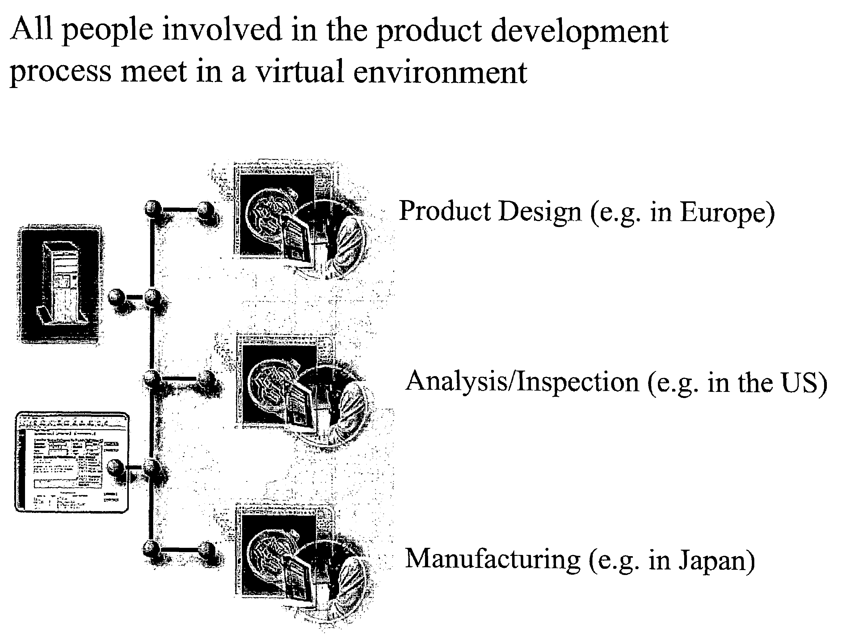
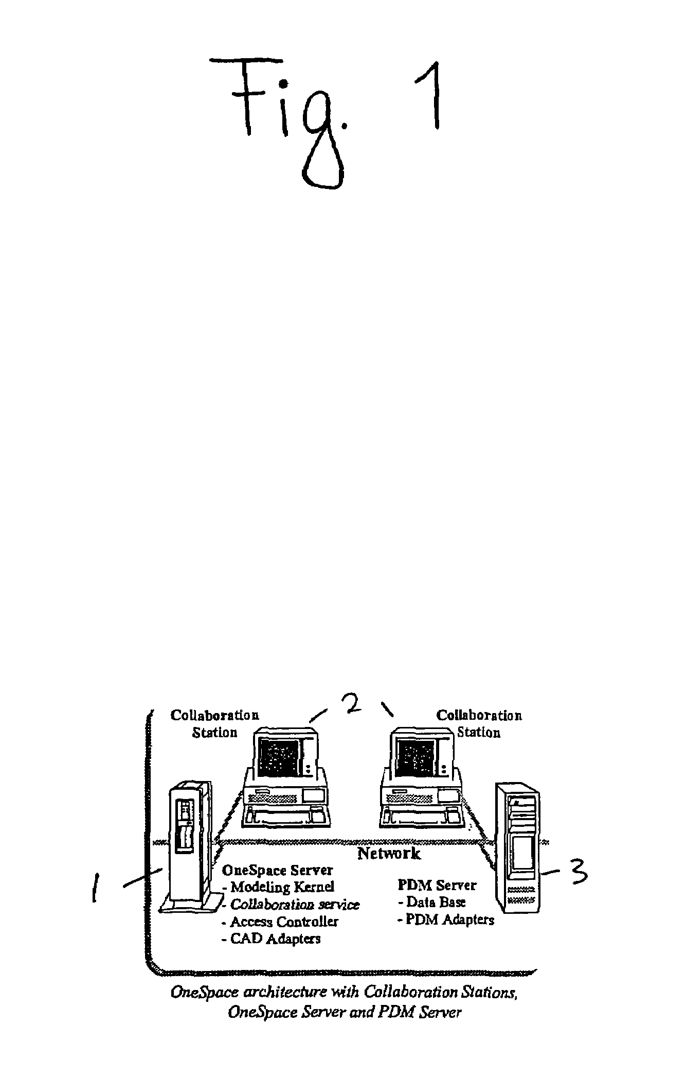
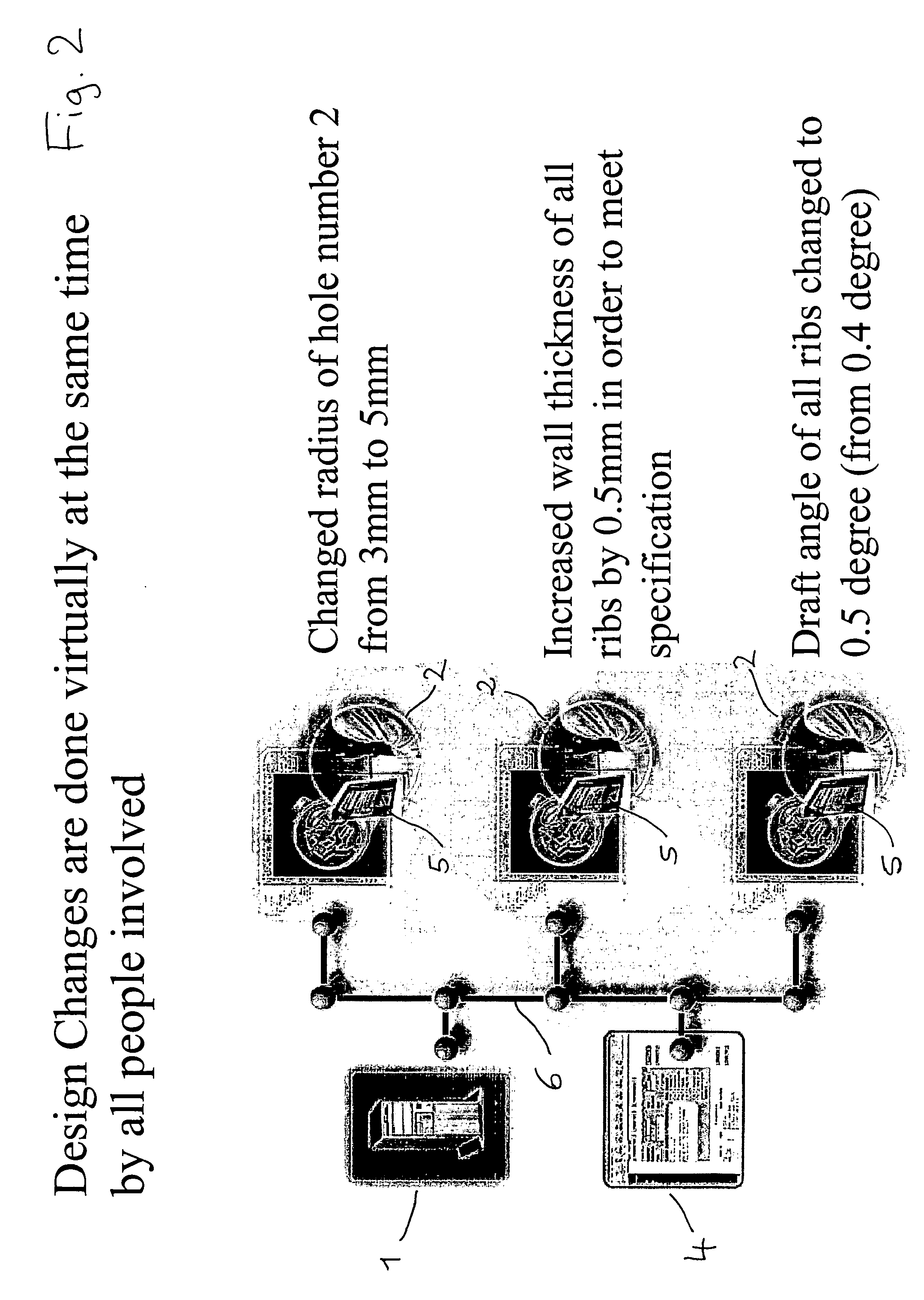
[0047]The architecture of a ‘OneSpace’ collaboration system can be seen in FIG. 1. The system consists of a collaboration server 1 and clients or ‘collaboration stations’2. These components can be located anywhere in a global network. FIG. 2 shows an example where a design is being discussed and worked on simultaneously by a designer based in Europe, an analyst / inspector based in the USA and a manufacturer based in Japan.

[0048]The client is the front-end for the integrated collaboration application modules. Any participant or client (provided they have the appropriate authority) can trigger an upload of data into the server for synchronous real-time viewing, inspection, conference, mark-up and collaborative editing of the 3D model. Results of the session can be downl...


PUM


Abstract

Every type of change in a CAD generated object is automatically and chronologically protocoled so that the object directly includes an abstract description of the history of the object independent of the CAD module used. This is particularly advantageous with decentralized CAD systems in which several constructors / designers are working together on the same draft, but located in different places. At the end of a session, the object history, i.e. the changes which have taken place, are directly exported, together with the object data, into the destination system. The abstract description is in a form independent of the system used.

Description

FIELD OF THE INVENTION[0001]The present invention relates to a system for computer aided design (CAD), and particularly for a web-based, real-time collaborative CAD design process.BACKGROUND[0002]Design projects in a whole range of fields generally require a collaboration of individuals and a coordination of information and tasks.[0003]Most engineering design results from the joint efforts of a highly qualified team of engineers, designers, marketing specialists, etc. The people working on any particular product may belong to different companies, using different CAD systems and may be based in widely differing locations.[0004]It is thus difficult and time-consuming for these people to exchange data and to discuss design ideas and modifications. Decisions can be delayed when members of the team are unable to travel or attend meetings. Furthermore, because members of the design team can be located all over the world, much expense and time can be spent in travelling to meetings to disc...

Claims


Application Information

Patent Timeline
Patent Type & Authority Patents(United States)
IPC IPC(8): G06F17/50
CPCG06F17/50G06F2217/04G06F2111/02G06F30/00
Inventor FREITAG, STEFAN
Owner PARAMETRIC TECH CORP
Learn More