Eureka AIR delivers breakthrough ideas for toughest innovation challenges, trusted by R&D personnel around the world.

Stamp and device for receiving an inking pad

Inactive Publication Date: 2006-07-04
TRODAT GMBH
View PDF9 Cites 44 Cited by
  • Summary
  • Abstract
  • Description
  • Claims
  • Application Information

AI Technical Summary

Benefits of technology

[0008]The objective of the present invention is to structure the arrangement and / or design of the stamp pad and its carrier device in such a way that it is possible to replace the stamp pad without the risk or with a low risk of the user or the surroundings getting covered in ink.

Problems solved by technology

However, when removing the stamp pad from the housing it has not been possible in some cases to prevent the user getting his hands covered in ink.

Method used


Image

  • Stamp and device for receiving an inking pad
  • Stamp and device for receiving an inking pad
  • Stamp and device for receiving an inking pad

Examples


Embodiment Construction

[0042]It should be established first of all that in the variously described embodiments the same parts are given the same reference numbers and the same component names, whereby the disclosures contained throughout the description can be applied analogously to the same parts with the same reference numbers and same component names. Furthermore, the details of position used in the description, such as e.g. top, bottom, side etc. relate to the Figure being described at the time, and if there is a change of position should be transferred accordingly to the new position. In addition, individual features or combinations of features from the different embodiments shown and described examples represent in themselves independent, inventive or inventive solutions.

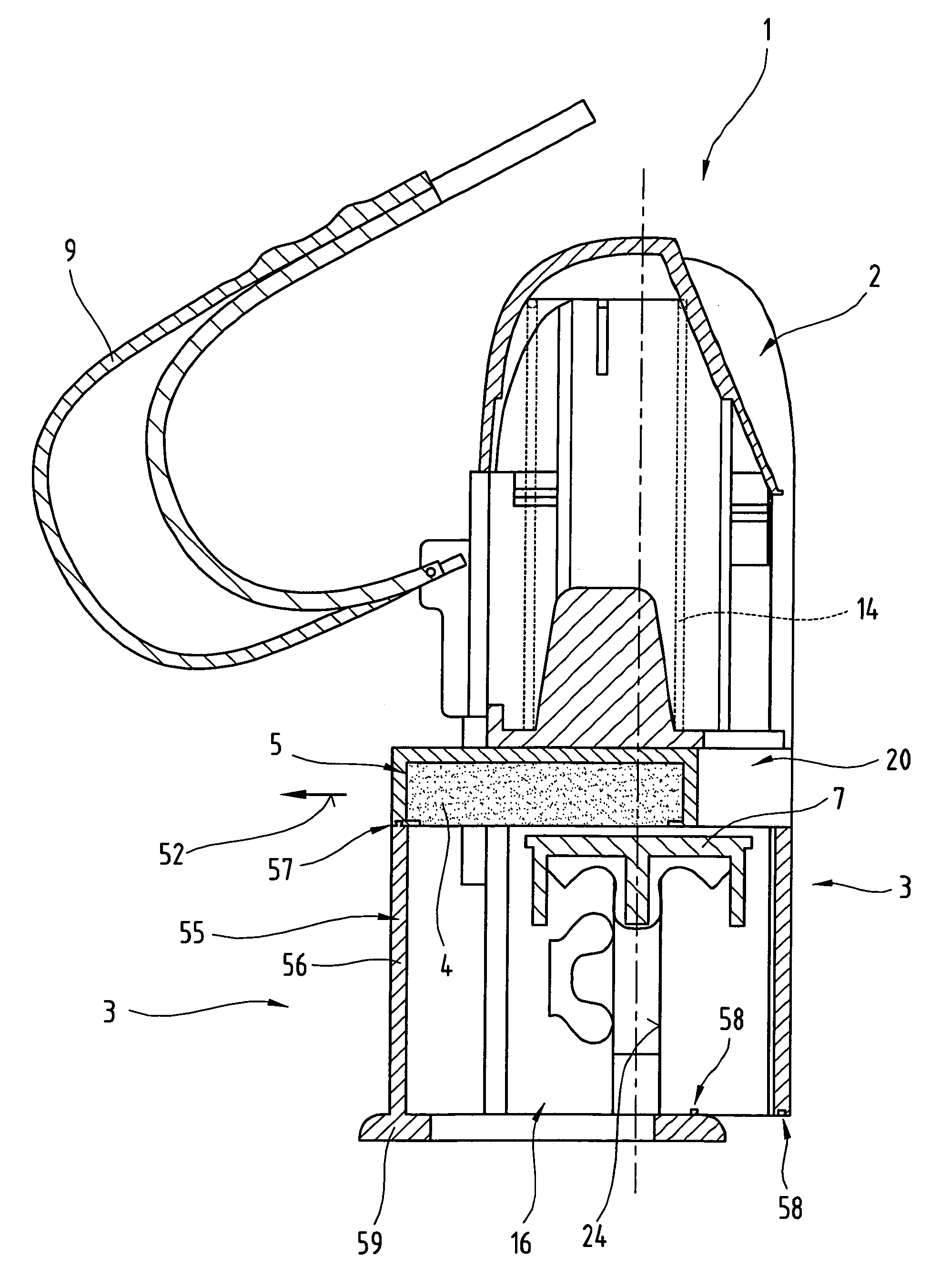
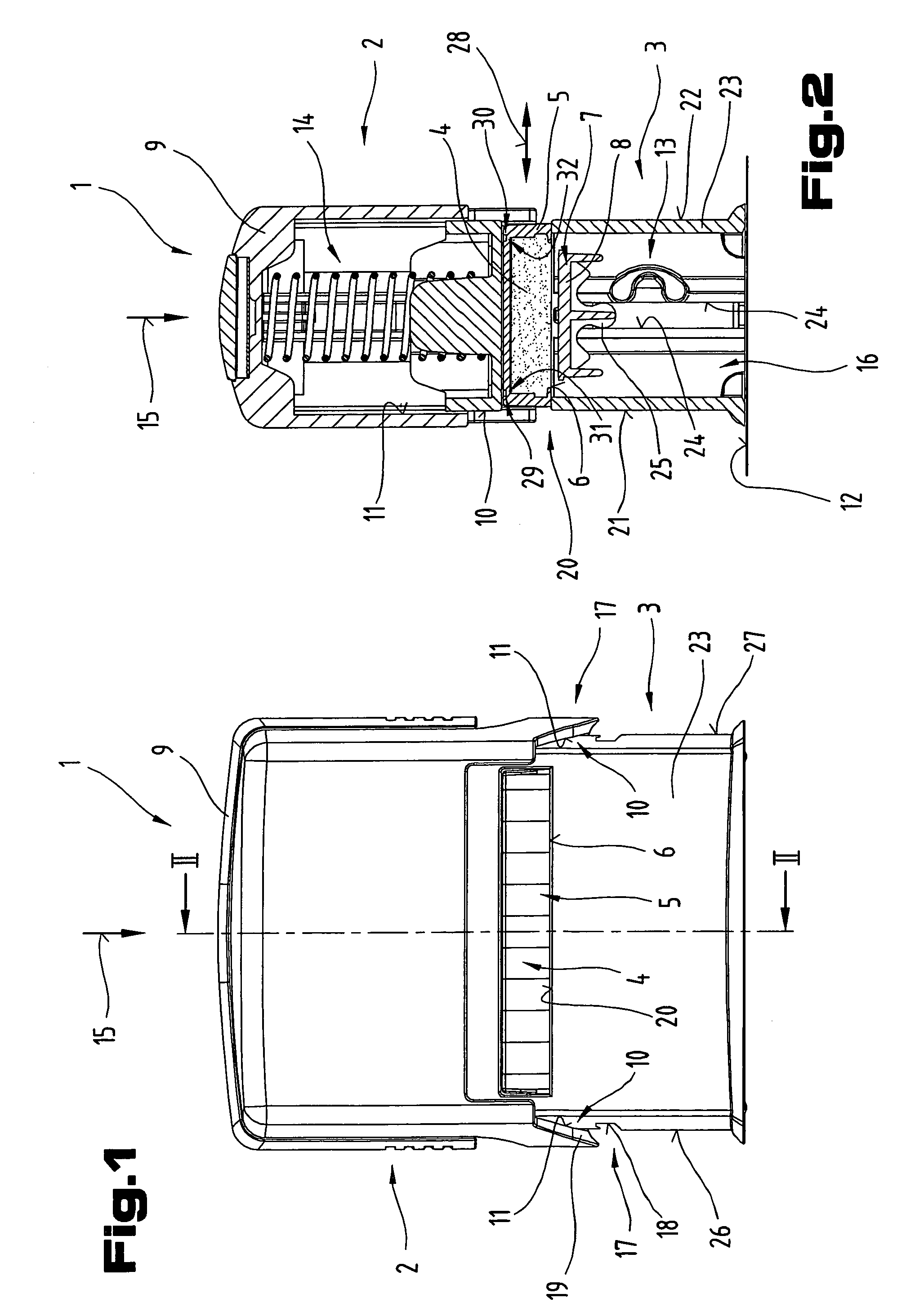
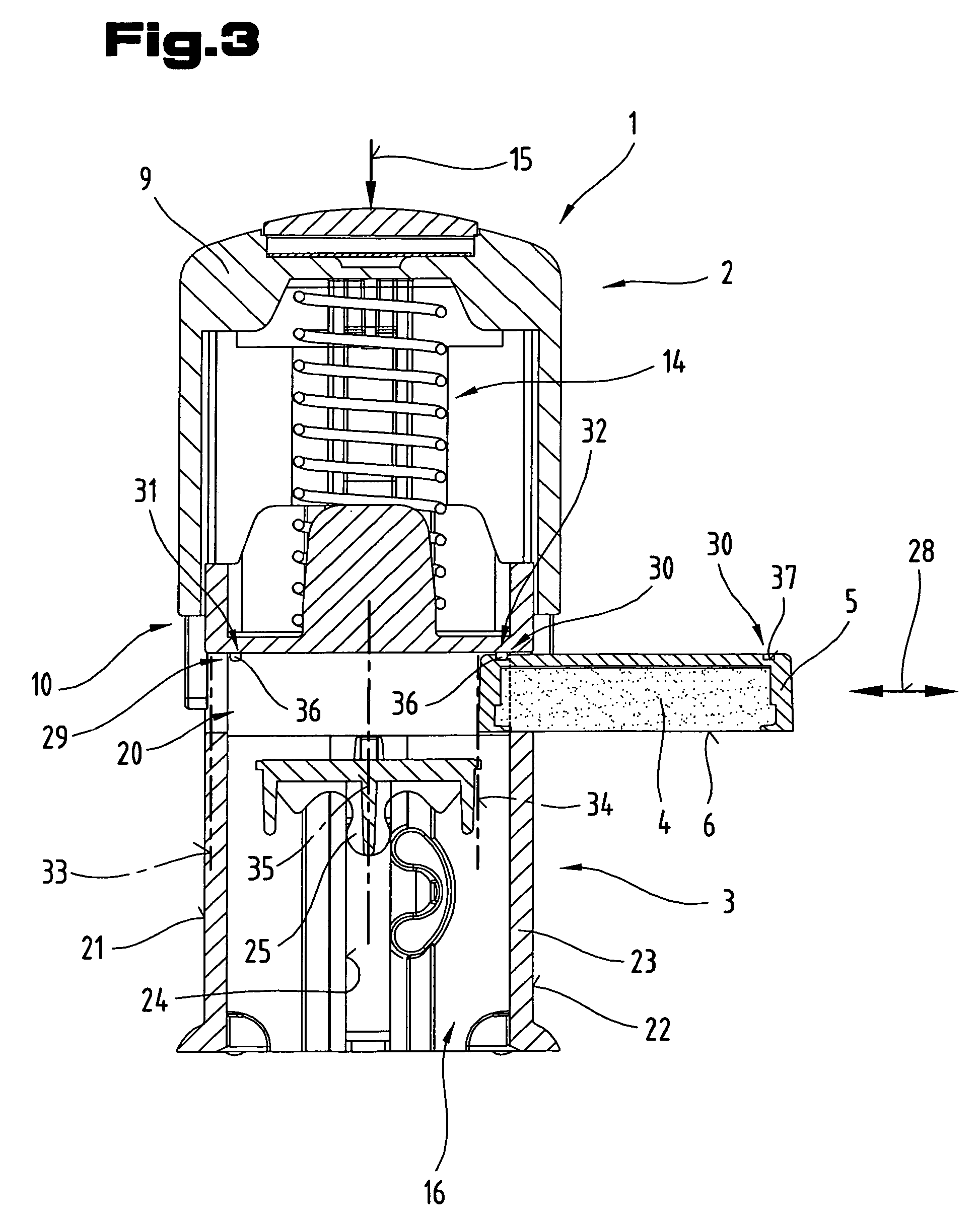
[0043]In FIGS. 1 to 3 a stamp 1 designed according to the invention is illustrated in simplified, schematic view.

[0044]Said stamp 1 is designed here as a so-called self-inking stamp in which the stamp surface is automatically refill...


PUM


Abstract

A device comprising: a holding fixture (23) for a carrier device (5) of a stamp pad (40, in particular for a stamp (1) with a pivotable printing plate carrier (8), in which a shaft (20) with an approximately rectangular cross section is arranged. The carrier device (5) for the stamp pad (4) is mounted therein, and if necessary can be pushed out relative to the shaft (20). A holding device (31) positions the carrier device (5) relative to the guide track of the shaft (20) in its position of work or use (33). A further holding device (32) enables the carrier device (5) together with the stamp pad (4) to be positioned in a replacement or maintenance position (34) remote from the position of work or use (33), and to be restrictable relative to the shaft (20) on how far it can be pushed out. The further holding device (32) can, if necessary, be deactivated by applying increased displacement forces on the carrier device (5).

Description

CROSS REFERENCE TO RELATED APPLICATIONS[0001]Applicants claim priority under 35 U.S.C. §119 of Austrian Application Nos. A 805 / 2002 and A 57 / 2003, filed May 27, 2002 and Jan. 17, 2003, respectfully. Applicants also claim priority under 35 U.S.C. §365 of PCT / AT03 / 00138 filed May 14, 2003. The international application under PCT article 21(2) was not published in English.BACKGROUND OF THE INVENTION[0002]1. Field of the Invention[0003]The invention relates to a device comprising a holding fixture for a carrier device of a stamp pad, as well as a stamp.[0004]2. Description of the Prior Art[0005]Various holding fixtures for stamp pads or carrier devices are already known, for example from the Applicant's WO 01 / 83227 A1. A holding fixture of this kind is positioned in a lower part of a multiple part stamp housing. The lower part of the stamp housing is designed in the shape of a hollow prism and has a rectangular cross section. In the direction of the longitudinal axis of the hollow prism...

Claims


Application Information

Patent Timeline
IPC IPC(8): B41K1/42B41K1/40B41K1/54
CPCB41K1/54B41K1/40
Inventor ZINDL, PETERHAIBERGER, MANFRED
Owner TRODAT GMBH
Why Eureka
Eureka Blog
Learn More