Capacitor for Resonant Circuits in Power Applications

Active Publication Date: 2020-05-07
POLITECNICO DI TORINO
View PDF0 Cites 0 Cited by
  • Summary
  • Abstract
  • Description
  • Claims
  • Application Information

AI Technical Summary

Benefits of technology

The patent describes a new technique for making extremely thin and large capacitors, which is beneficial for heat dissipation and space occupation. The use of a multilayer printed circuit board technology also reduces costs. This technique overcomes voltage limitations of current capacitors, avoids the need for multiple batteries, and offers smaller dimensions.

Problems solved by technology

In such coupling conditions, the resonance of the coil-capacitor system results in a considerable increase in the voltage across the terminals of these two elements.
The different types of capacitors currently in use in such applications cannot always tolerate voltages higher than one or two kilovolts (kV).
The capacitors currently available on the market are bulky, massive and heavy.
The thermal characteristics resulting from these physical features are such as to often require the use of liquid-cooling systems, leading to a more complex mechanical structure of the resonator.
Such low tolerated voltage values require that capacitor batteries be resorted to, resulting in higher costs, greater dimensions, more complex connections and increased complexity of the heat sinking systems.
20%, but may be as low as 5% for particularly accurate or selectable implementations, which are even more costly.

Method used


Image

  • Capacitor for Resonant Circuits in Power Applications
  • Capacitor for Resonant Circuits in Power Applications
  • Capacitor for Resonant Circuits in Power Applications

Examples


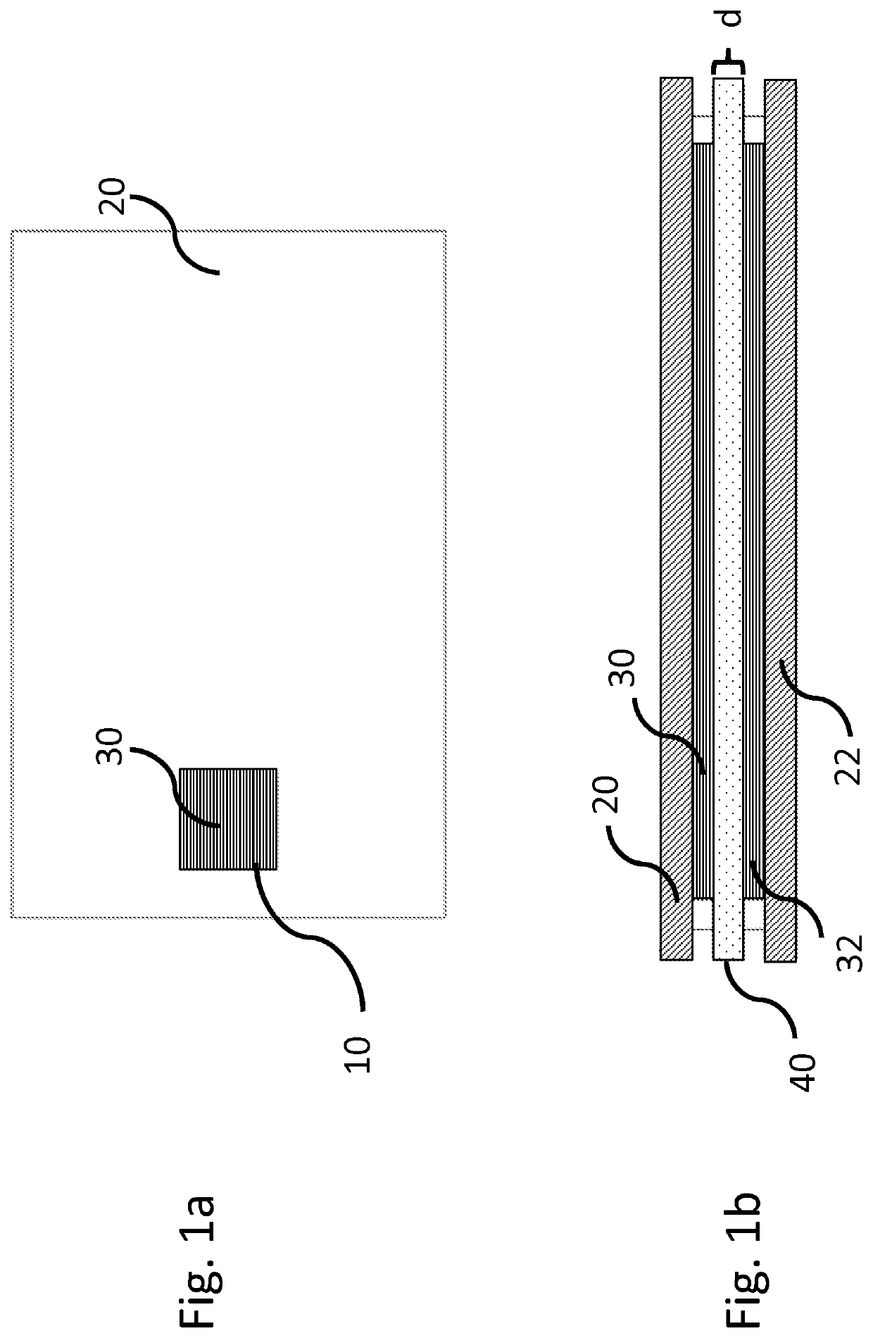
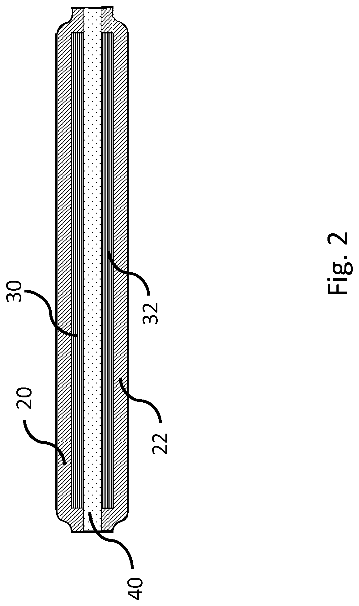
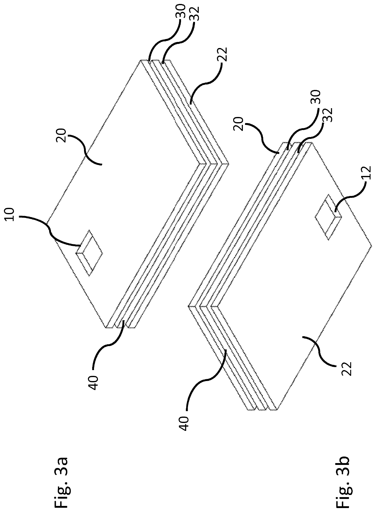
Embodiment Construction

[0046]The following description will illustrate various specific details useful for a deep understanding of some examples of one or more embodiments. The embodiments may be implemented without one or more of such specific details or with other methods, components, materials, etc. In other cases, some known structures, materials or operations will not be shown or described in detail in order to avoid overshadowing various aspects of the embodiments. Any reference to “an embodiment” in this description will indicate that a particular configuration, structure or feature is comprised in at least one embodiment. Therefore, the phrase “in an embodiment” and other similar phrases, which may be present in different parts of this description, will not necessarily be all related to the same embodiment. Furthermore, any particular configuration, structure or feature may be combined in one or more embodiments as deemed appropriate.

[0047]The references below are therefore used only for simplicit...


PUM

PropertyMeasurementUnit
Temperatureaaaaaaaaaa
Thicknessaaaaaaaaaa
Dielectric polarization enthalpyaaaaaaaaaa

Abstract

A capacitive element is manufactured by using the multilayer printed circuit board technology. The body of the element includes a layer of dielectric material interposed between two layers of conductive material arranged on opposite sides of the layer of dielectric material. Each layer of conductive material is in turn covered, on its free side, with an external covering layer. The material for making the layer of dielectric material is chosen among materials having: —a dielectric permeability εr>1, —a dielectric rigidity k>100 kV / mm, and —a loss figure Df≤0.002. Furthermore, the dimensions of the layer of dielectric material are greater than the dimensions of the layers of conductive material, so as to limit the edge effects that might cause discharge phenomena and make the capacitive element flexible.

Description

FIELD OF INVENTION[0001]The present invention relates to techniques for manufacturing capacitors, and in particular for manufacturing capacitors for resonant circuits in power applications.[0002]More in detail, the invention can be employed in all industrial applications that require the use of highly inductive loads made resonant by capacitive compensation.[0003]Some classic application examples include all processes related to heating, welding, hardening and melting by electromagnetic induction.[0004]One application that is naturally addressed by the invention concerns inductive recharging systems for electric vehicles / systems, whether moving or stationary, which require the use of compensation / resonance capacitors both for the transmitting coil installed on the ground and for the receiving coil installed aboard the vehicle / system.[0005]More in detail, the invention relates to a solution for manufacturing capacitors for medium-voltage, high-frequency and high-current industrial ap...

Claims


Application Information

Patent Timeline
IPC IPC(8): H01G4/33H01G4/224H01G4/14H01G4/12H05K1/16
CPCH05K1/162H01G4/224H01G4/14H02J50/12H01G4/33H01G4/1209H01G4/18H01G4/186H05K3/4602
Inventor GUGLIELMI, PAOLOFRENCHI, FABIOCIRIMELE, VINCENZO
Owner POLITECNICO DI TORINO
Why Eureka
Try Eureka