Floating drive-on-watercraft dock

a technology of watercraft docks and drive-on docks, which is applied in the direction of groynes, vessel parts, special-purpose vessels, etc., can solve the problems of difficult and time-consuming construction of docks, piers, etc., and require significant upkeep, and is subject to the rise and fall of water level of water bodies, and is expensive to manufacture and assemble. , complex in shap

Active Publication Date: 2006-07-04
E Z DOCK
View PDF18 Cites 36 Cited by
  • Summary
  • Abstract
  • Description
  • Claims
  • Application Information

AI Technical Summary

Benefits of technology

[0009]The side wall glide assemblies in one embodiment comprise a base member having a plate sized and shaped to be received and held in the side wall roller pocket and a transverse member which extends up from the base. A bracket is selectively positionable horizontally along the transverse member. An axle is pivotally received in a selected vertical position on the bracket, and roller members are received on opposite ends of the axle. The ability to selectively position the bracket along the transverse member and to selectively position the axle on the bracket allows for the side wall roller assembly to be configured for different shaped watercraft and watercraft hulls. In a second embodiment of the glide assembly, the rollers are replaced with a pad which the hull of a watercraft can slide over. A third embodiment of the glide assembly comprises two base members positioned in spaced apart side pockets. A track of rollers extends between and is mounted to the two base members.

Problems solved by technology

Such docks, piers, etc. are difficult and time consuming to construct and require significant upkeep.
Additionally, if the dock is not a floating dock, it is further subject to the rise and fall of the water level of the water body in which the dock is located.
However, they are generally complicated in shape and expensive to manufacture and assemble.

Method used


Image

  • Floating drive-on-watercraft dock
  • Floating drive-on-watercraft dock
  • Floating drive-on-watercraft dock

Examples


Embodiment Construction

[0041]The following detailed description illustrates the invention by way of example and not by way of limitation. This description will clearly enable one skilled in the art to make and use the invention, and describes several embodiments, adaptations, variations, alternatives and uses of the invention, including what we presently believe is the best mode of carrying out the invention. Additionally, it is to be understood that the invention is not limited in its application to the details of construction and the arrangements of components set forth in the following description or illustrated in the drawings. The invention is capable of other embodiments and of being practiced or being carried out in various ways. Also, it is to be understood that the phraseology and terminology used herein is for the purpose of description and should not be regarded as limiting.

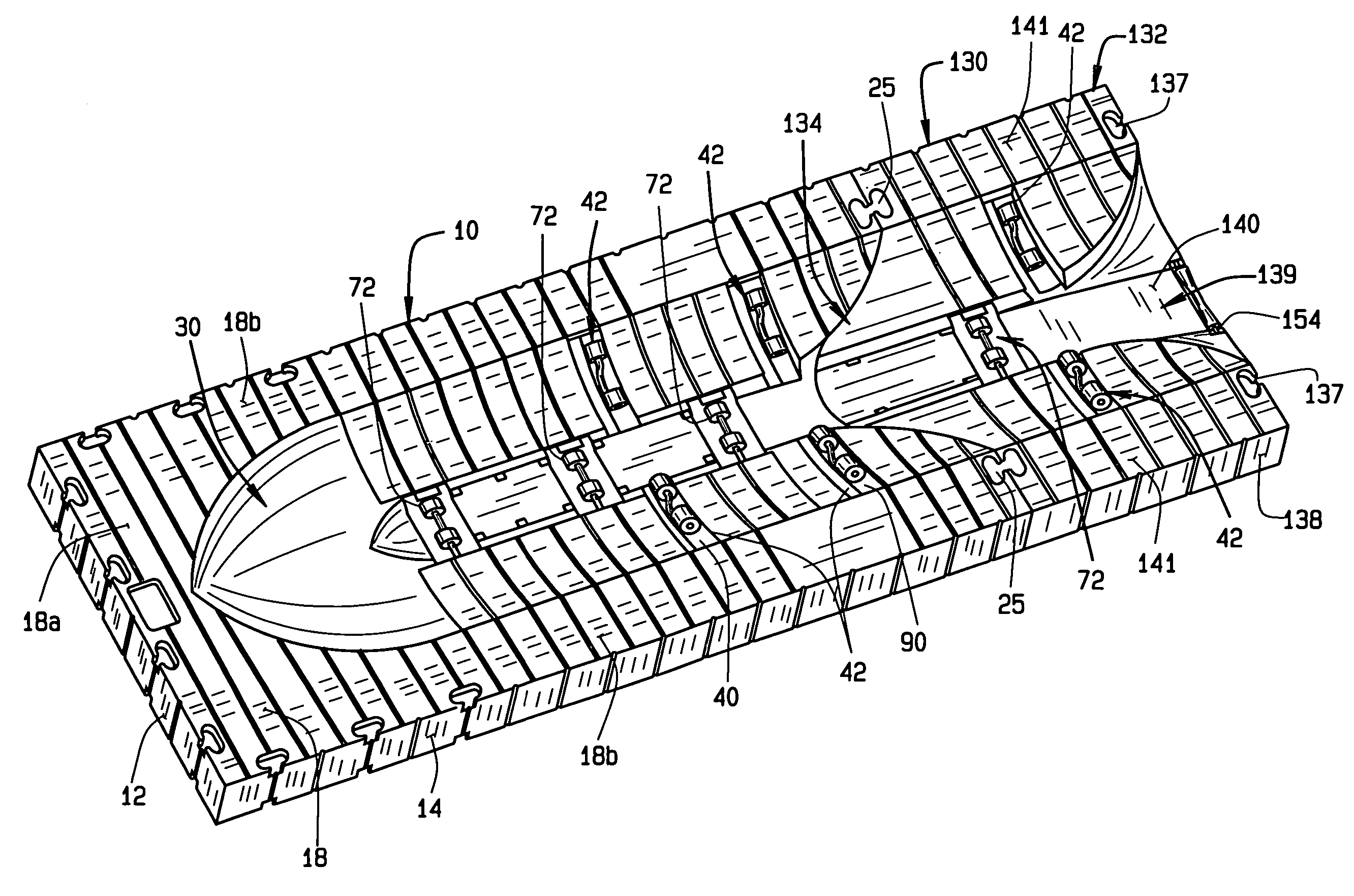
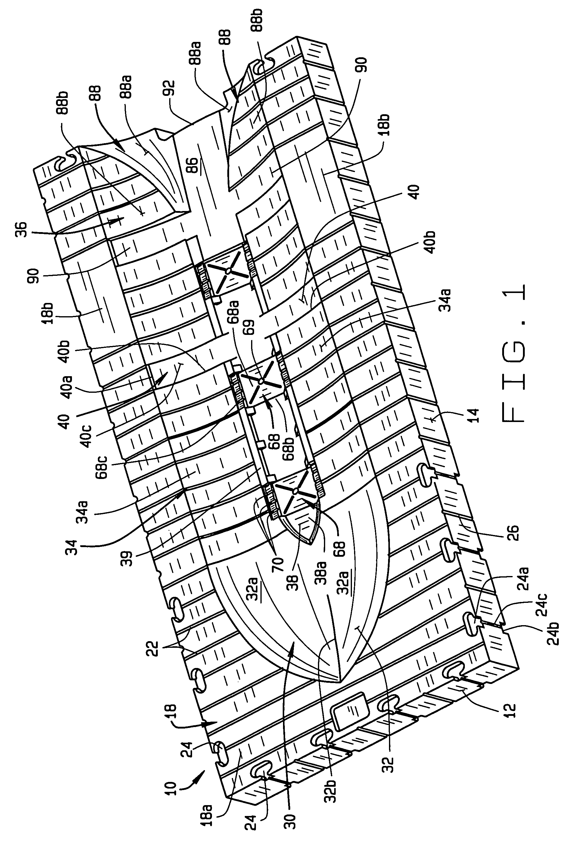
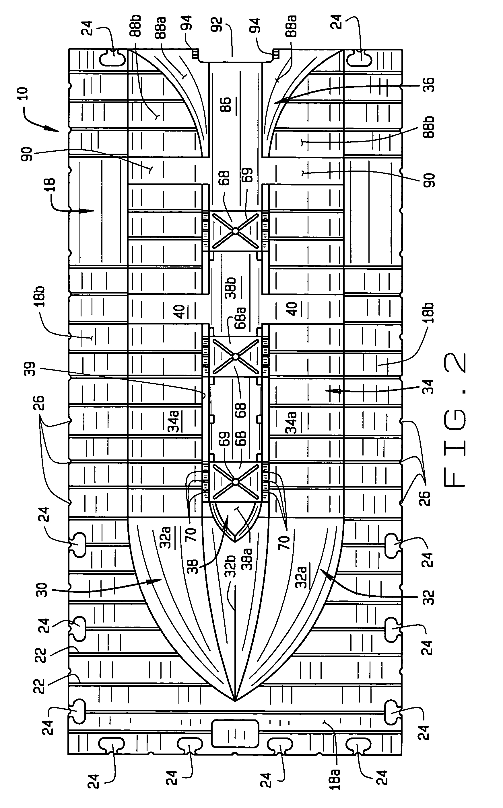
[0042]An illustrative embodiment of a floating drive-on watercraft dock body or section 10 sized to receive a small waterc...


PUM


Abstract

A floating drive-on watercraft dock comprises a one-piece molded body defining a watercraft receiving area. The watercraft receiving area includes roller assemblies on the bottom of the watercraft receiving area and glide assemblies on the sides of the watercraft receiving area. The roller and glide assemblies can be easily removed and replaced for servicing of the watercraft dock. An extension unit is provided which can be connected to the watercraft dock body. The extension unit includes an extension body and a tongue extending from the extension body. The tongue is sized and shaped to have a bottom surface complementary to the entrance to the watercraft receiving area of the watercraft dock body. The extension unit also includes a watercraft receiving area, which, when the extension unit is connected to the watercraft dock, increases the length of the watercraft receiving area.

Description

CROSS-REFERENCE TO RELATED APPLICATIONS[0001]This application claims priority to Provisional Application No. 60 / 542,140 filed Feb. 6, 2004, entitled Personal Watercraft Dock, and which is incorporated herein by reference. This application is also a Continuation-In-Part of application Ser. No. 29 / 211,862, filed Aug. 23, 2004 and entitled Floating Drive-On Boat Dock; application Ser. No. 29 / 211,860, filed Aug. 23, 2004 and entitled Floating Drive-On Boat Dock Extension; and application Ser. No. 29 / 211,867, filed Aug. 23, 2004 and entitled Extended Floating Drive-On Boat Dock, all of which are incorporated herein by reference.STATEMENT REGARDING FEDERALLY SPONSORED RESEARCH OR DEVELOPMENT[0002]Not Applicable.BACKGROUND OF THE INVENTION[0003]This invention relates to floating docks, piers, etc., and, in particular, to a floating drive-on watercraft dock on which watercraft, such as personal watercraft and small boats can be dry-docked.[0004]Watercraft docks commonly comprise pilings whi...

Claims


Application Information

Patent Timeline
Patent Type & Authority Patents(United States)
IPC IPC(8): B63B35/40B63C1/02E02B3/06
CPCB63C1/02B63C1/00E02B3/06
Inventor OSTRENG, TROYMOODY, LAWRENCE
Owner E Z DOCK
Why Eureka
Try Eureka