Modular tank unit for ship, barge and rail transportation

a technology for rail transportation and modules, applied in the field of modules or tanks, can solve the problems of lack of terminal facilities or tank farms, lack of active means, economic detriment, etc., and achieve the effect of convenient and simple installation or removal

Inactive Publication Date: 2009-05-28
DEBERARDINIS NICHOLAS W
View PDF8 Cites 29 Cited by
  • Summary
  • Abstract
  • Description
  • Claims
  • Application Information

AI Technical Summary

Benefits of technology

[0052]The sloping bottom wall of the tank, within the tank framework, defines a fluid handling compartment within which is located a pump and fluid handling unit having connection hoses and conduit that are connected with a tank discharge located at the bottom center of the tank. The pump and fluid handling unit is provi

Problems solved by technology

Many locations have the ability to make liquid products from local raw materials, but currently lack a terminal facility or tank farm to store the manufactured liquid products pending the arrival of an appropriate carrier.
Therefore, these locations export raw solid materials instead of manufactured liquid products, to their economic detriment.
Further, this inventor is not aware of the existence of portable products containers that are of specific dimensional and volumetric ranges to permit their transportation by cargo vessels, hopper barges and railway hopper cars.
The above containers are not specifically designed to serve as a dual purpose transportation container and terminal for storing and dispensing bulk liquid products, including flammable or other hazardous liquid products.
None prov

Method used


Image

  • Modular tank unit for ship, barge and rail transportation
  • Modular tank unit for ship, barge and rail transportation
  • Modular tank unit for ship, barge and rail transportation

Examples


Embodiment Construction

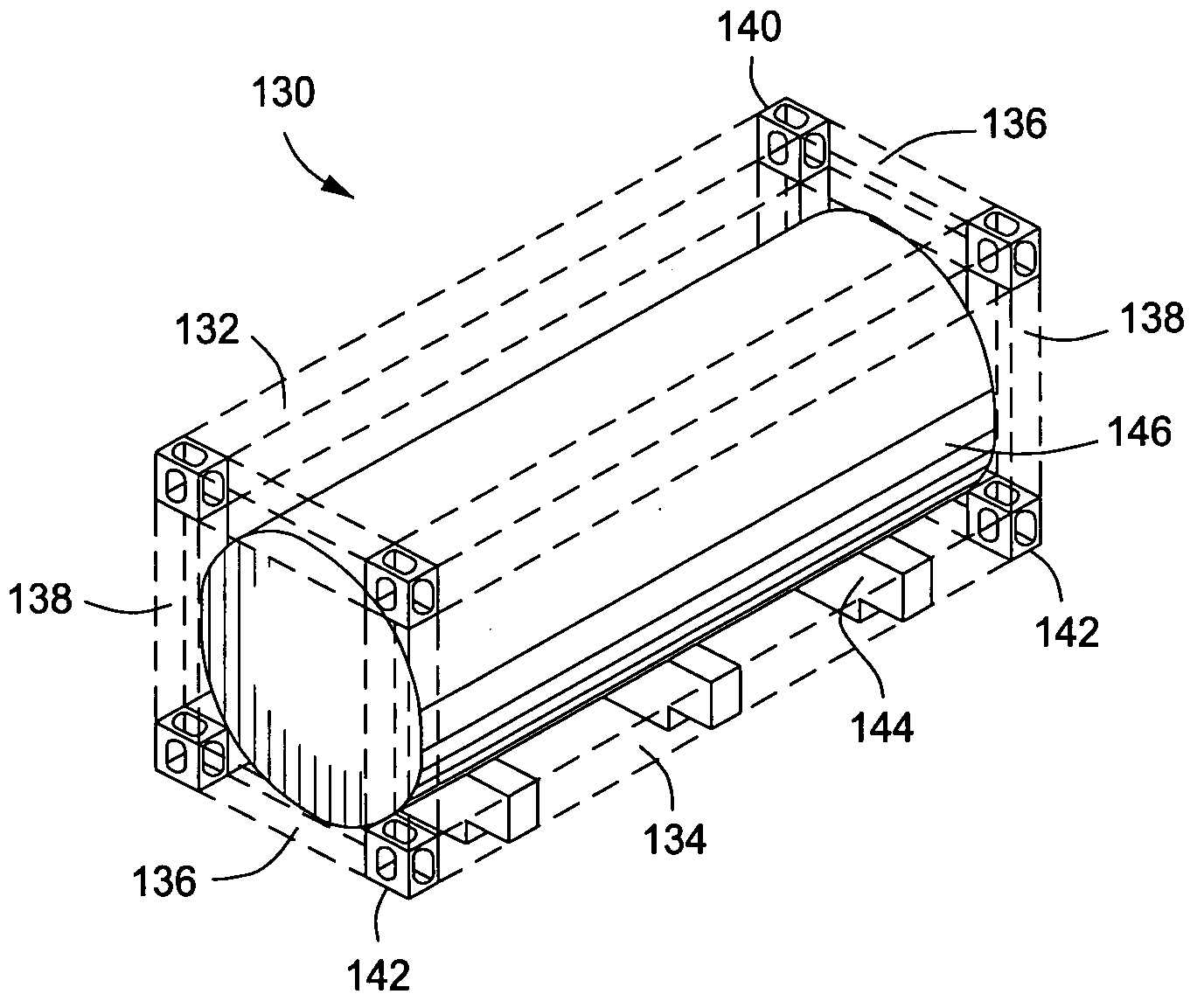
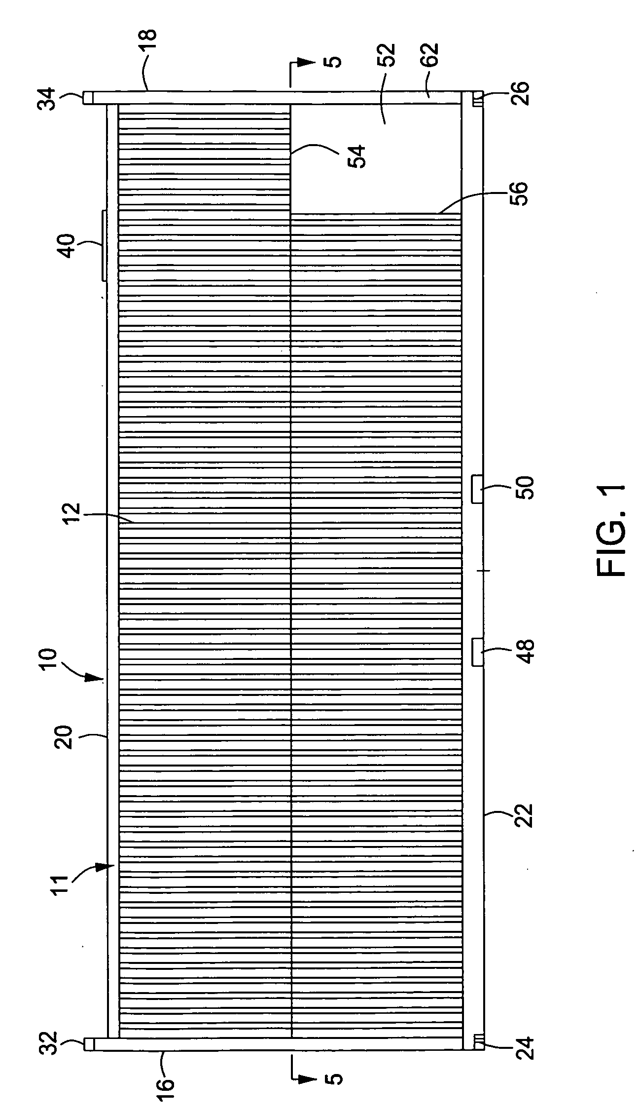
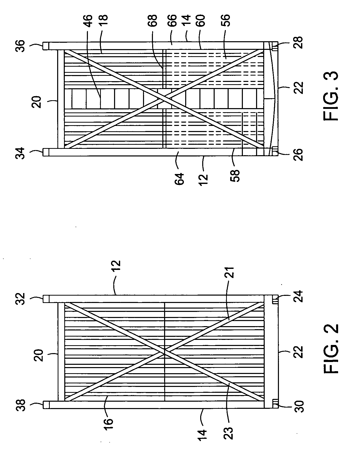
[0075]Referring now to the drawings and first to FIG. 1, a modular tank unit is shown generally at 10 and is preferably of generally rectangular configuration, having a tank framework structure shown generally at 11 and providing a pair of generally parallel side walls 12 and 14 and a pair of generally parallel end walls 16 and 18. The modular tank unit further defines a top wall structure 20 and a bottom wall structure 22. Though shown to be of generally rectangular configuration, it is to be borne in mind that the modular tank unit may have other forms without departing from the spirit and scope of the present invention. Typically, however, the modular tank unit is intended to be received and locked within the container cells of a cargo vessel, hopper barge or train car; thus the footprint that is defined by its bottom structure is typically the same as that of a conventional cargo container. The bottom portion of the framework of the modular tank unit defines corner fittings 24, ...


PUM

PropertyMeasurementUnit
Lengthaaaaaaaaaa
Lengthaaaaaaaaaa
Widthaaaaaaaaaa

Abstract

A modular tank unit for utilizing vessels of opportunity to serve as carriers for transportation and handling of specialty liquids or flowable particulate products or to serve as a terminal ashore receiving and dispensing to truck, rail, barge or other receiving facilities. The modular tank unit has a rectangular intermodal framework of predetermined dimension and tare weight permitting its transportation by cargo vessel, hopper barge and by rail for positioning inland or at shore facilities. A tank may be adapted for other modes of transportation and may be removably secured within the rectangular framework. The modular tank unit in its smaller dimension can be transported empty by rail and can be positioned in the field by portable crane. The modular tank unit defines a pump compartment having a pumping and draining manifold and portable pump and valve assembly for fluid handling, enabling the modular tank unit to be “active” for power energized pumping or “passive” for gravity discharge.

Description

RELATED INVENTIONS[0001]Portable liquid cargo tanks or containers capable of being employed for instant terminaling and ship conversion have been developed as exemplified by U.S. Pat. Nos. 5,365,980 and 5,460,208, both issued to Nicholas W. deBerardinis, the inventor of the subject matter presented herein.BACKGROUND OF THE INVENTION[0002]1. Field of the Invention[0003]The present invention relates generally to containers or tanks within which liquid or fluidized solid particulate cargo can be stored and can be transported by differing types of cargo carriers including ship, open inland hopper barge and rail transportation systems. The containers or tanks are designed to be releasably retained by the cargo carrier systems and are transferable from one container adapted cargo carrier system to another. More particularly, the present invention concerns a self-contained liquid cargo container having integrated therewith a replaceable pumping and valve controlled manifold system for load...

Claims


Application Information

Patent Timeline
IPC IPC(8): B65D88/12B65D88/10
CPCB65D88/128B65D88/54B65D90/0033B65D2590/0091B65D90/24B65D90/44B65D90/22
Inventor DEBERARDINIS, NICHOLAS W.
Owner DEBERARDINIS NICHOLAS W
Why Eureka
Try Eureka