Fuel injector with non-metallic tip insulator

a fuel injector and non-metallic technology, applied in the direction of machines/engines, mechanical equipment, casings, etc., can solve the problems of fuel spray halting, increased heat transfer so as to reduce the overheating of the injector tip

Inactive Publication Date: 2006-07-04
CATERPILLAR INC
View PDF22 Cites 60 Cited by
  • Summary
  • Abstract
  • Description
  • Claims
  • Application Information

AI Technical Summary

Benefits of technology

[0008]In another aspect, the present invention provides a method of reducing injector tip overheating. This method includes the steps of providing

Problems solved by technology

During engine braking, however, fuel spray is halted and the injector tip is thus more susceptible to heat transfer from the air in the cylinder.
However, this boosted compression of the air tends to heat the injector tip substantially, particularly in two-cycle boosting applications.
Because the valve seat is subjected to repeated impacts by the needle valve member, softening of the valve seat material can result in quicker wear and distortion of the seat, leading to improper sealing.
Additionally, weakening of the metal in the area of the valve seat can accelerate fatigue, which can eventually lead to tip breakage and catastrophic engine failure.
Exotic metal alloys wit

Method used


Image

  • Fuel injector with non-metallic tip insulator
  • Fuel injector with non-metallic tip insulator
  • Fuel injector with non-metallic tip insulator

Examples


Embodiment Construction

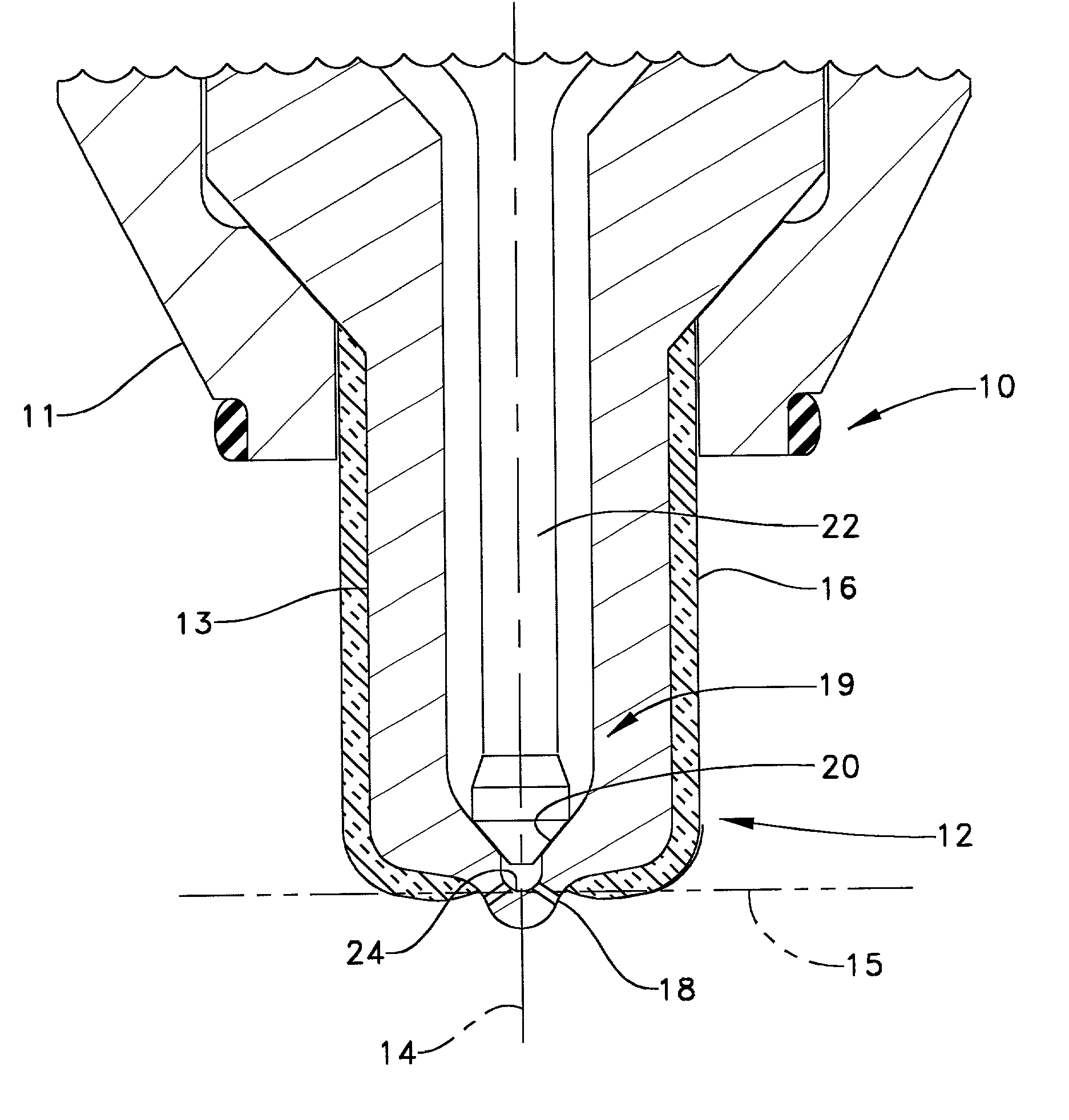
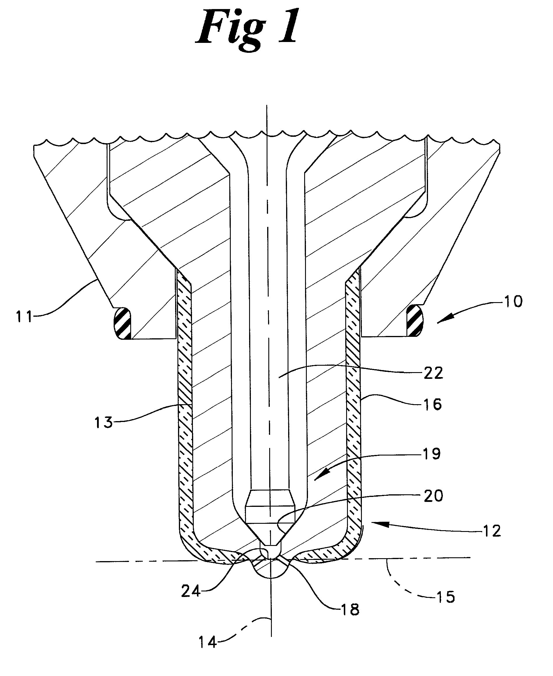
[0012]Referring to FIG. 1, there is shown a partial sectioned side view of a fuel injector 10 according to the present invention. Injector 10 has an injector body 11 with a metallic tip 12. A needle valve 19 is positioned within injector 10 and alternately opens or closes a valve seat 20. A non-metallic insulator 16 is attached to a portion of the outer surface 13 of injector tip 12. Injector body 11 defines a plurality of nozzle outlets 18 which fluidly connect to a sac 24 below valve seat 20.

[0013]Injector body 11 has a centerline 14 which is perpendicular to a plane 15. Plane 15 intersects injector body 11 and centerline 14 at a point which preferably lies between valve seat 20 and nozzle outlets 18. In the preferred embodiment, insulator 16 is attached to the portion of the outer surface 13 of injector tip 12 which lies above plane 15 such that nozzle outlets 18 are not covered. FIG. 1 also shows that an outwardly directed centerline from the nozzle outlets 18 does not intersect...


PUM


Abstract

A fuel injector is provided which has an injector body with a metallic tip having an outer surface. A non-metallic insulator, such as a ceramic, is attached to the tip and covers a portion of the outer surface. Injector tip overheating can be a problem, especially during sustained two-cycle boosted engine compression release braking. In addition, injector tip overheating can be a problem when an engine is experiencing simultaneous engine compression release braking and exhaust braking.

Description

TECHNICAL FIELD[0001]The present invention relates generally to fuel injectors, and more particularly to an injector with a non-metallic insulator attached to a portion of the injector tip.BACKGROUND ART[0002]In most diesel engines, fuel injectors are positioned such that at least a portion of the injector tip protrudes into the engine combustion space. The injector tip is thus exposed to the high temperatures and pressures from fuel combustion and engine compression release braking. In these injectors which employ a needle valve to control the fuel spray, the valve seat can potentially be heated to close to its tempering temperature during engine compression release braking. During normal engine operation, the fuel travelling through the injector tip carries heat away. During engine braking, however, fuel spray is halted and the injector tip is thus more susceptible to heat transfer from the air in the cylinder.[0003]Depending on the capabilities of the individual system, engine br...

Claims


Application Information

Patent Timeline
IPC IPC(8): B05B1/30F02F7/00F02M53/04
CPCF02M53/04F02F7/0087
Inventor SHINOGLE, RONALD D.
Owner CATERPILLAR INC
Why Eureka
Try Eureka