Ball- and -socket joint

a ball-and-socket joint technology, applied in the direction of couplings, rod connections, mechanical devices, etc., can solve the problems of leakage due to pretension, high cost of bellows plastic material anchoring, etc., and achieve the effect of improving the seat of the sealing ring

Inactive Publication Date: 2006-07-04
ZF LEMFOERDER METALLWAREN AG
View PDF17 Cites 20 Cited by
  • Summary
  • Abstract
  • Description
  • Claims
  • Application Information

AI Technical Summary

Benefits of technology

[0003]The object of the present invention is to improv

Problems solved by technology

Loosening of the seat of the sealing ring may develop in this ball-and-socket joint because of adhesion problems between the sealing ring and the sealing bellows, which may lead to leakage.
The

Method used


Image

  • Ball- and -socket joint
  • Ball- and -socket joint
  • Ball- and -socket joint

Examples


Embodiment Construction

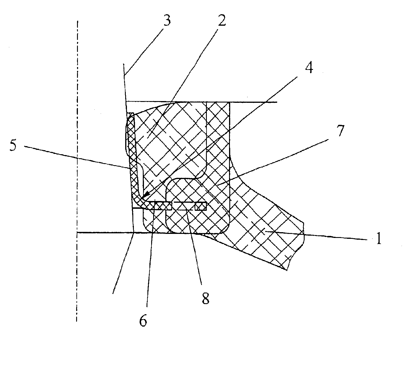
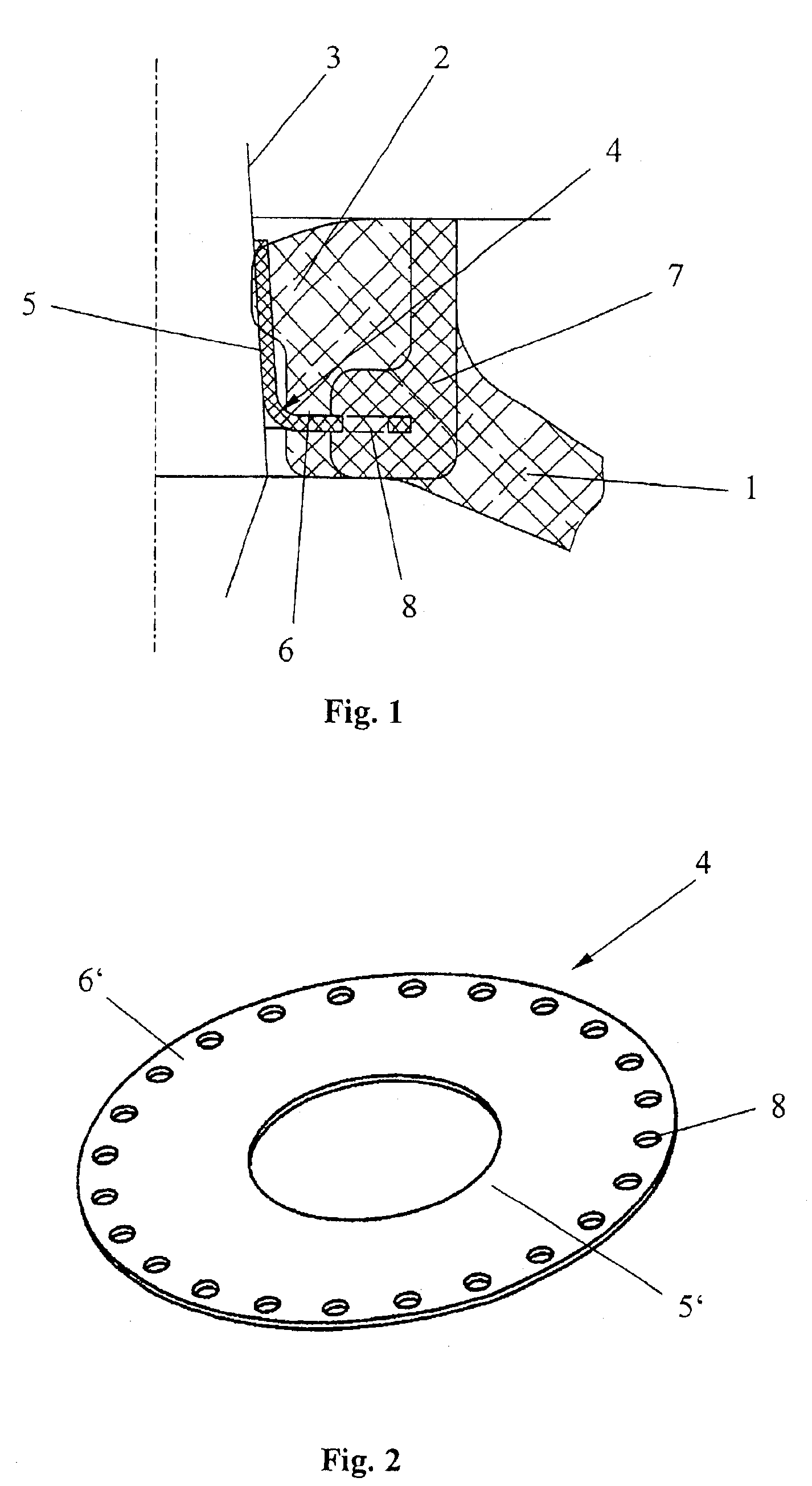
[0021]Referring to the drawings in particular, FIG. 1 shows a partial sectional view of an embodiment of the ball-and-socket joint according to the present invention, according to which a sealing bellows 1 is mounted with its upper end having a pressing area 2 on a ball pivot 3. The sealing bellows 1 is mounted slidably on the ball pivot 3 via a sealing ring 4 having two legs, wherein a first of the two legs 5 is in contact with the ball pivot 3 under tension and the second leg 6 meshes with the wall of the sealing bellows 1. The tension with which the first leg 5 is in contact with the ball pivot is determined by the internal stress of the sealing ring 4, on the one hand, and by the pressing area 2, which presses the first leg 5 against the ball pivot 3 in addition to the internal stress.

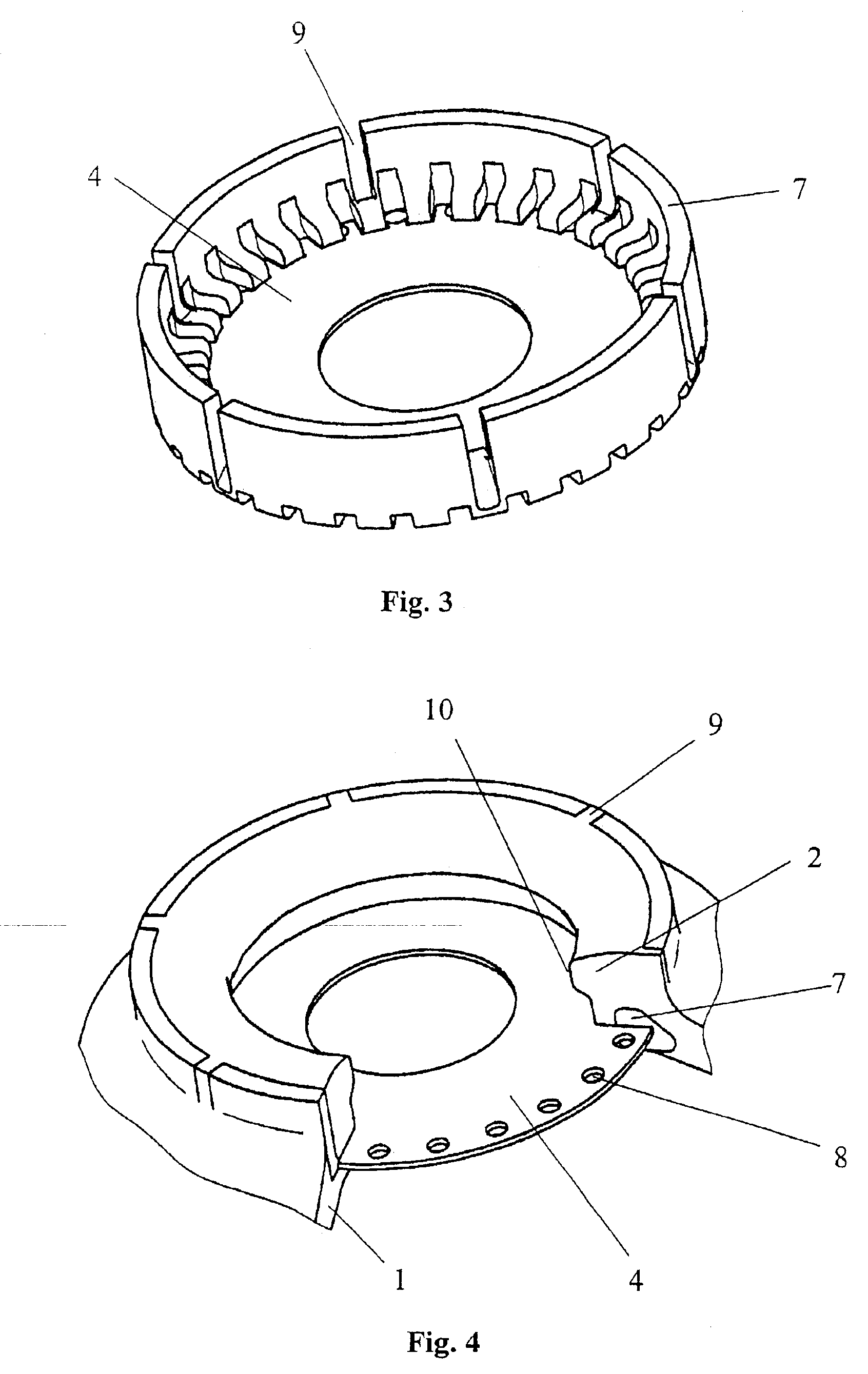
[0022]An anchoring ring 7, around which the elastomer material of the sealing bellows 1 is partially molded, is fastened in the wall of the sealing bellows 1. The second leg 6 of the sealing ring 4...


PUM


Abstract

A ball-and-socket joint has a housing, a ball pivot (3) mounted pivotably in the housing, and a sealing bellows (1), which is fastened to the housing and is mounted on the ball pivot (3) slidably via a sealing ring (4) provided with two legs (5, 6). A first leg (5) of the two legs (5, 6) is in contact with the ball pivot (3) under tension and the second leg (6) meshes with the wall of the sealing bellows (1). The second leg (6) is, furthermore, fastened in an anchoring ring (7) arranged at least partially in the wall of the sealing bellows (1).

Description

FIELD OF THE INVENTION[0001]The present invention pertains to a ball-and-socket joint with a housing a ball pivot mounted pivotably in the housing, and a sealing bellows, which is fastened to the housing and is mounted on the ball pivot slidably via a sealing ring having two legs, wherein a first of the two legs is in contact with the ball pivot under tension or force and the second leg meshes with the wall of the sealing bellows.BACKGROUND OF THE INVENTION[0002]Such a ball-and-socket joint is disclosed in DE 198 43 063 C1, in which a circular groove, which is engaged by the second leg of the sealing ring, is provided on the inner side of the sealing bellows. Loosening of the seat of the sealing ring may develop in this ball-and-socket joint because of adhesion problems between the sealing ring and the sealing bellows, which may lead to leakage. The anchoring of the plastic material in the material of the bellows is also expensive. Furthermore, the creep of the plastic, which can be...

Claims


Application Information

Patent Timeline
IPC IPC(8): F16J15/52F16C11/06F16J3/04
CPCF16C11/0671F16J3/042Y10T403/32729Y10T403/315Y10T403/31Y10T403/32311F16C11/06
Inventor ABELS, OLAFGROGER, DIETER
Owner ZF LEMFOERDER METALLWAREN AG
Why Eureka
Try Eureka