Disc brake piston cap and disc brake equipped therewith

a disc brake and piston cap technology, applied in the direction of bellows, engine components, mechanical equipment, etc., can solve the problems of cap not being able to protect the inside of the piston from liquid or solid matter attack, cap not folding back correctly, boot deterioration,

Active Publication Date: 2014-04-24
CHASSIS BRAKES INT BV
View PDF4 Cites 8 Cited by
  • Summary
  • Abstract
  • Description
  • Claims
  • Application Information

AI Technical Summary

Benefits of technology

[0009]the brake piston can operate freely while at the same time sealing against external elements and not be pushed into a braking position by the pressure of the hot air trapped when the brakes are supposed to be being released.

Problems solved by technology

It is possible that the cap will fail to fold back correctly in the groove of the caliper.
It is then exposed to contact with the metal parts of the brake, the temperature of which may reach high values which, after a certain time, cause the boot to deteriorate.
This boot, once torn, is no longer able to protect the inside of the piston against attack by liquid or solid matter, dust or the like.

Method used


Image

  • Disc brake piston cap and disc brake equipped therewith
  • Disc brake piston cap and disc brake equipped therewith
  • Disc brake piston cap and disc brake equipped therewith

Examples


Embodiment Construction

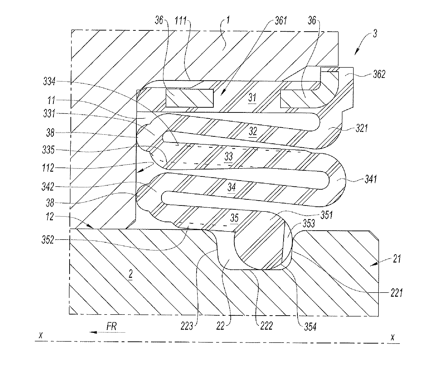
[0036]One subject of the invention is a disc brake piston cap housed between the caliper and the piston to separate the volume on the outside of the brake from the volume on the inside and to protect the piston.

[0037]The cap and the disc brake to which it is fitted will be described hereinafter.

[0038]FIG. 1 is an axial half section of the caliper 1 of the disc brake along the axis x-x of the piston 2 housed in the bore 12. The piston 2 is a cylindrical sleeve the front face 21 of which presses against the brake pad along an outline in the form of a circular annulus so as to push the pad against the brake disc. The brake disc and pad, neither depicted, are in the right-hand part of FIG. 1. The caliper 1 comprises an annular groove 11 accepting the cap 3 fixed to the piston 2 in a groove 22. The cap 3 has symmetry of revolution generated by rotating this section about the axis x-x.

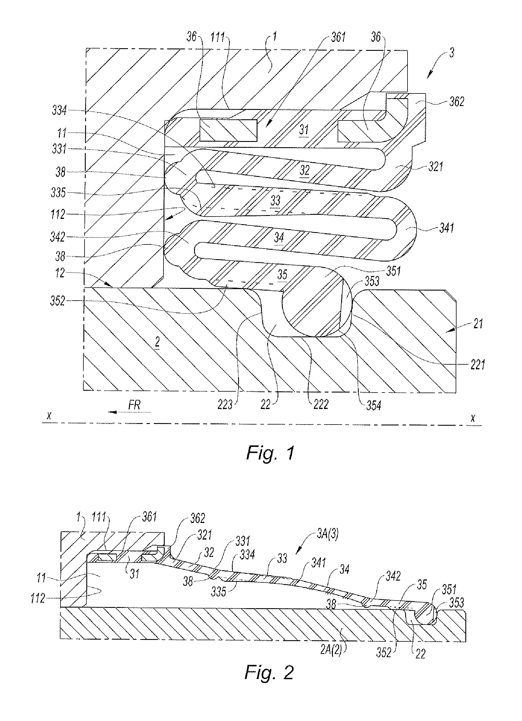
[0039]In the fully deployed state according to FIG. 2, the cap 3 has a frustoconical overall shape 3A, th...


PUM


Abstract

Disc brake piston cap (3) interposed between the caliper (1) and the piston (2) to protect the piston (2). The cap (3) has a bulge (351) on the inner fold (35) which is engaged in the groove (22) of the piston (2), and has an overmoulded insert (31) fixed to the annular groove (11) of the caliper. The folded cap (3), with the overmoulded insert (31), intermediate folds (33, 34) and an outer fold (32), comprises longitudinal ribs (352) on the face of the inner fold (35) to stiffen this fold and allow air to pass from the inside to the outside around the bulge (351) of the inner fold (35), housed in the groove (22).

Description

FIELD OF THE INVENTION[0001]The present invention relates to a disc brake piston cap interposed between the caliper and the piston to protect the piston and the bearing surface of the caliper at the mouth of the bore accommodating the piston against attack (from liquids and solids), this cap being made up of a bellows-style concertina-folded boot having an outer edge and an inner edge to be housed in an annular groove of the caliper at the mouth of the bore accommodating the piston, the outer edge of the cap being fixed to the caliper at the outer side of the annular groove and its inner edge being provided with a bulge housed in a groove of the piston.[0002]Such a cap, also referred to as a dust boot or dust gaiter, seals the inside of the brake piston inside the caliper with respect to the outside while at the same time allowing the piston to complete its braking travel and taking account of how this travel evolves as the brake pads gradually wear.BACKGROUND OF THE INVENTION[0003]...

Claims


Application Information

Patent Timeline
Patent Type & Authority Applications(United States)
IPC IPC(8): F16D65/00
CPCF16D65/005F16D55/2265F16J3/042F16J3/046F16D2125/08
Inventor CHAMPION, PASCALBARRET, PHILIPPEDAGUZAN, FRANCOISBINDNER, THIERRY
Owner CHASSIS BRAKES INT BV
Why Eureka
Try Eureka