Connector

A connector and connector technology, applied in the direction of connection, conductive connection, fixed connection, etc., can solve the problems of troublesome handling, difficult cover placement, and ineffective installation work.

Inactive Publication Date: 2003-01-22
SUMITOMO WIRING SYST LTD
View PDF4 Cites 14 Cited by
  • Summary
  • Abstract
  • Description
  • Claims
  • Application Information

AI Technical Summary

Problems solved by technology

This causes trouble in processing
Also, it is difficult to place the cover in the correct position during assembly
This causes the installation to not work

Method used


Image

  • Connector
  • Connector
  • Connector

Examples


Embodiment Construction

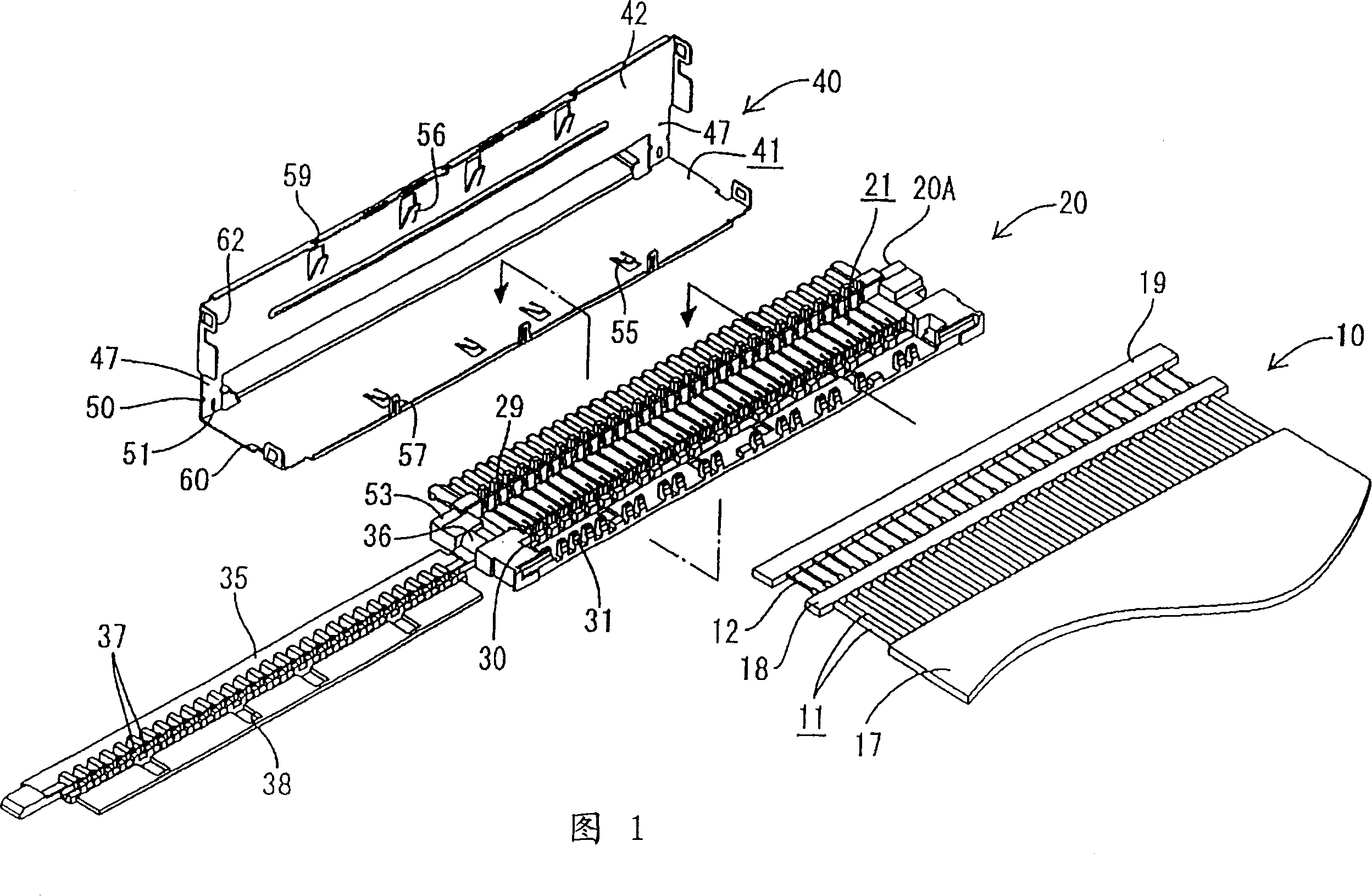
[0039] A first embodiment of the flat cable connector of the present invention will be described below with reference to FIGS. 1-11.

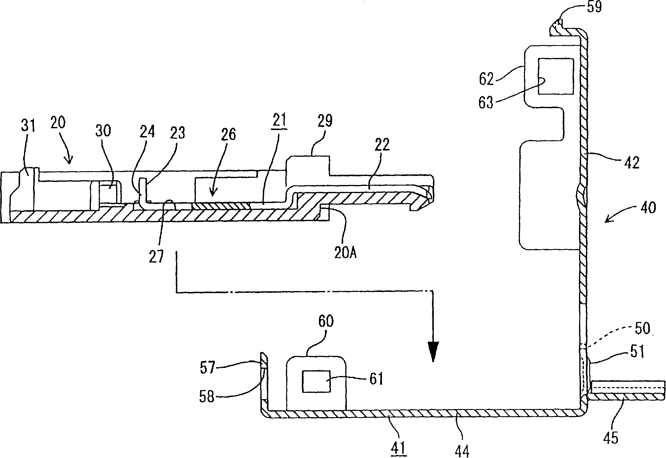
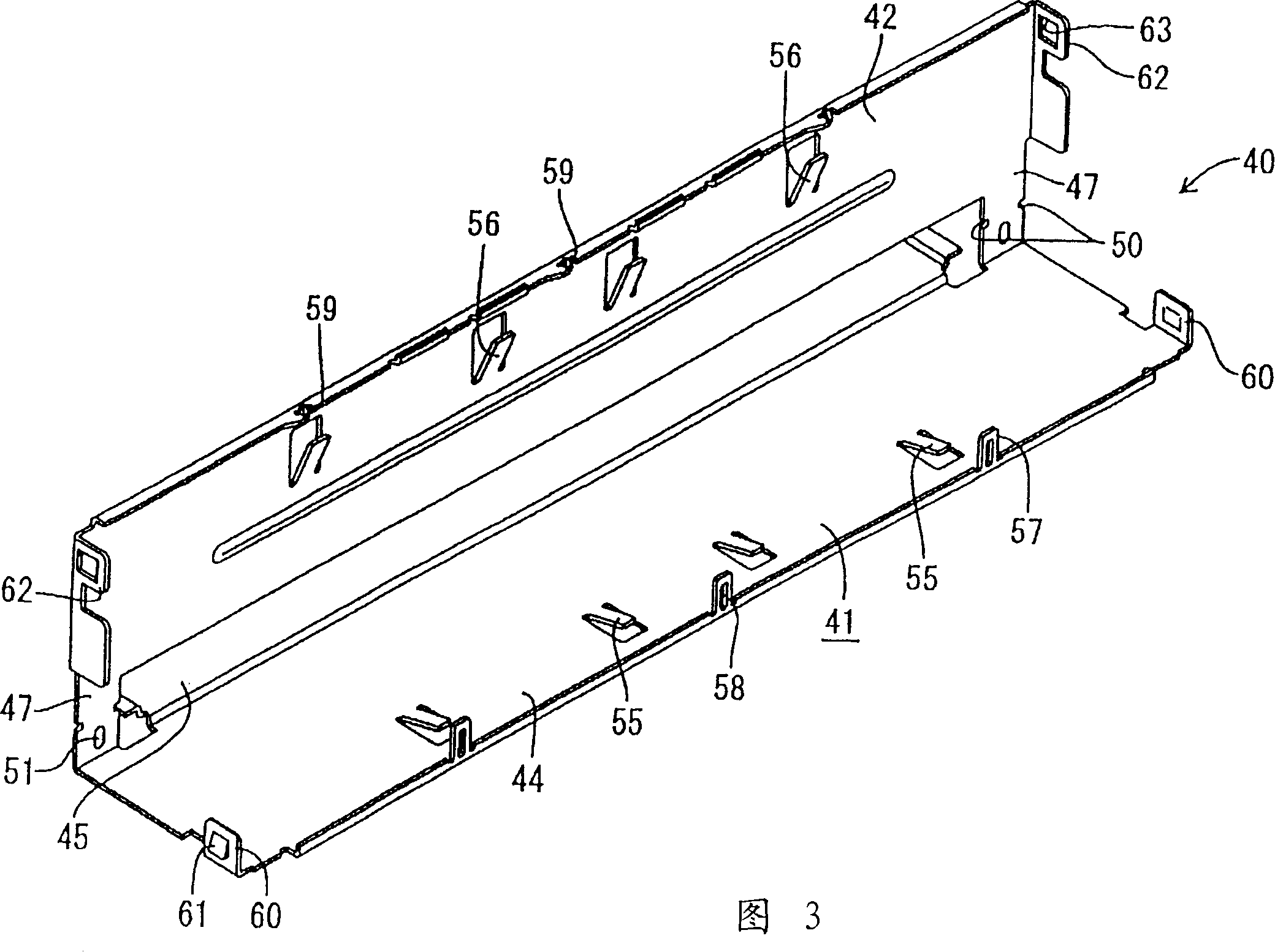
[0040] As shown in FIG. 1 , the connector in this embodiment basically includes a housing 20 to be connected to the end of the flat cable 10 and a shield shell 40 to be mounted to the housing 20 .

[0041] Such as Figure 6 As shown, the flat cable 10 includes a plurality of parallel shielded wires 11 spaced apart from each other by a predetermined distance. Each shielded wire 11 has a core wire 12 , an inner coating layer 13 surrounding the core wire 12 , a shielding layer 14 surrounding the inner coating layer 13 and an outer coating layer 15 surrounding the shielding layer 14 . A film 17 covers these wires 11 to form a ribbon-like structure. A short-circuit element 18 is fixed on the shielding layer 14 of each shielded wire 11 at the end of the flat cable 10 . The core wire 12 of each shielded electric wire 11 is exposed on the front side...


PUM


Abstract

A shield shell (40) has a base (41) and a lid (42) formed together through a pair of coupling pieces (47). A housing (20) on which terminal members (21) are mounted is put on the base (41), and distal ends of shielded electric wires (11) are mounted on the housing (20). A core (12) in each shielded electric wire (11) is brought into insulation displacement in the terminal member (21), and a cover (35) closes the housing (20). The lid (42) is bent at the coupling pieces (47). Thus, the housing (20) is disposed and locked between the base (41) and the lid (42). Contact pieces (56) on the lid (42) of the shield shell (40) pass through windows (38) in the cover (38) and elastically contact a short circuit member (18).

Description

technical field [0001] The present invention relates to a connector capable of being connected to the end of a flat cable having a plurality of parallel shielded wires, or to the end of a generally planar array of single shielded wires arranged side by side. technical background [0002] A known connector for flat cables is shown in Japanese Unexamined Patent Publication No. 2000-77123, which includes a housing for mounting terminals. These terminals are connected to the core wires of the shielded wires inside the flat cable. The known connector also includes a shielding shell having a base shell adapted to be mounted on the lower surface of the housing and a cover shell adapted to cover the upper surface of the housing. When this known connector is assembled, the base shell is first installed on the housing. The end of the flat cable is then mounted on the housing, followed by placement of the cover housing on the base housing. Therefore, the co...

Claims


Application Information

Patent Timeline
Patent Type & Authority Applications(China)
IPC IPC(8): H01R4/24H01R9/053H01R12/59H01R13/50H01R13/6581H01R13/6592
CPCH01R13/6581H01R9/053H01R13/658H01R13/6592H01R4/2425H01R13/501H01R12/594
Inventor 野吕丰
Owner SUMITOMO WIRING SYST LTD
Why Eureka
Try Eureka