Poultry picking finger and mounting structure

a technology of mounting structure and picking finger, which is applied in the field of picking fingers, can solve the problems of difficult and laborious removal and replacement of picking fingers, the elasticity of rubber decreases, and the fingers become less efficient in removing feathers, so as to facilitate quick and easy installation and removal.

Inactive Publication Date: 2006-07-04
BETTCHER INDUSTRIES
View PDF7 Cites 8 Cited by
  • Summary
  • Abstract
  • Description
  • Claims
  • Application Information

AI Technical Summary

Benefits of technology

[0011]The present invention features a picking finger having a mounting structure that facilitates quick and easy installation and removal of the picking finger from a mounting plate while providing for secure attachment of the picking finger to the mounting plate.

Problems solved by technology

Over time, the elasticity of the rubber decreases and the fingers become less efficient in removing feathers.
Removal and replacement of picking fingers is a difficult and labor intensive job.
The dangers of using a razor blade knife to cut the base of the finger while simultaneously bending the upper portion of the finger are self-evident.
Even with the application of lubricant, installation of picking fingers is problematic because significant force is required to pull the finger base portions through the circular openings to achieve the snap fit of the annular groove in the circular opening.
This problem is further exacerbated because, due to the design of defeathering machines, the positioning of mounting plates within the machine and the plurality of picking fingers on each mounting plate, there is little clearance available for removing and / or inserting picking fingers.
Aside from the expense, such tools have numerous disadvantages.
Further, such tools require operators to drag an air hose into a production area to operate the tools thereby risking contamination of the area.
Such tools are typically heavy and cumbersome to use.
As such, power picking finger cutters and installers have not been widely adopted in the poultry processing industry.

Method used


Image

  • Poultry picking finger and mounting structure
  • Poultry picking finger and mounting structure
  • Poultry picking finger and mounting structure

Examples


first embodiment 100

First Embodiment 100 of Picking Finger

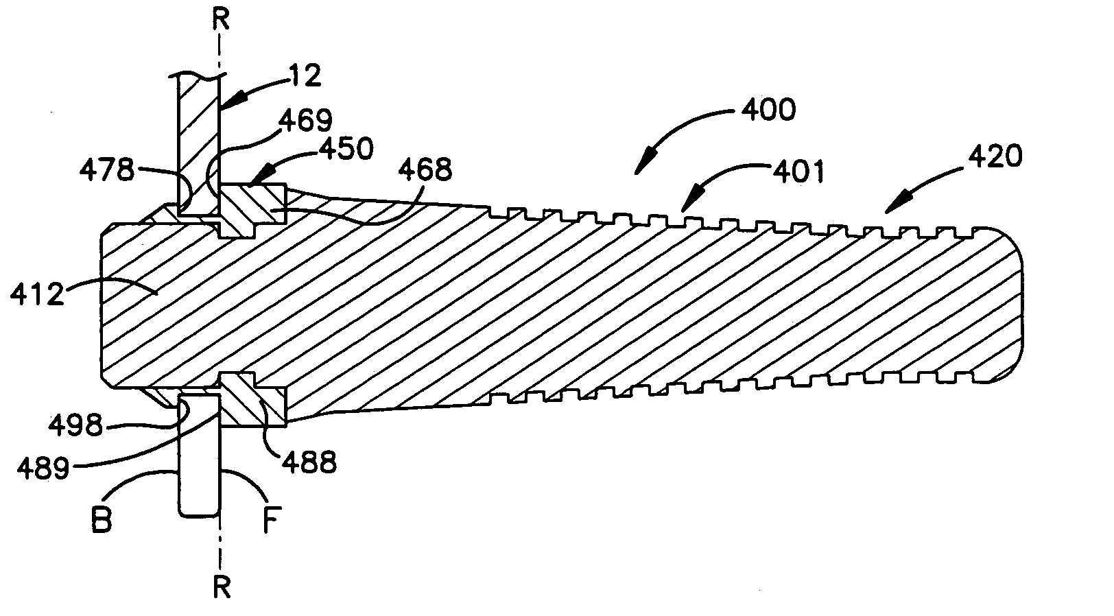
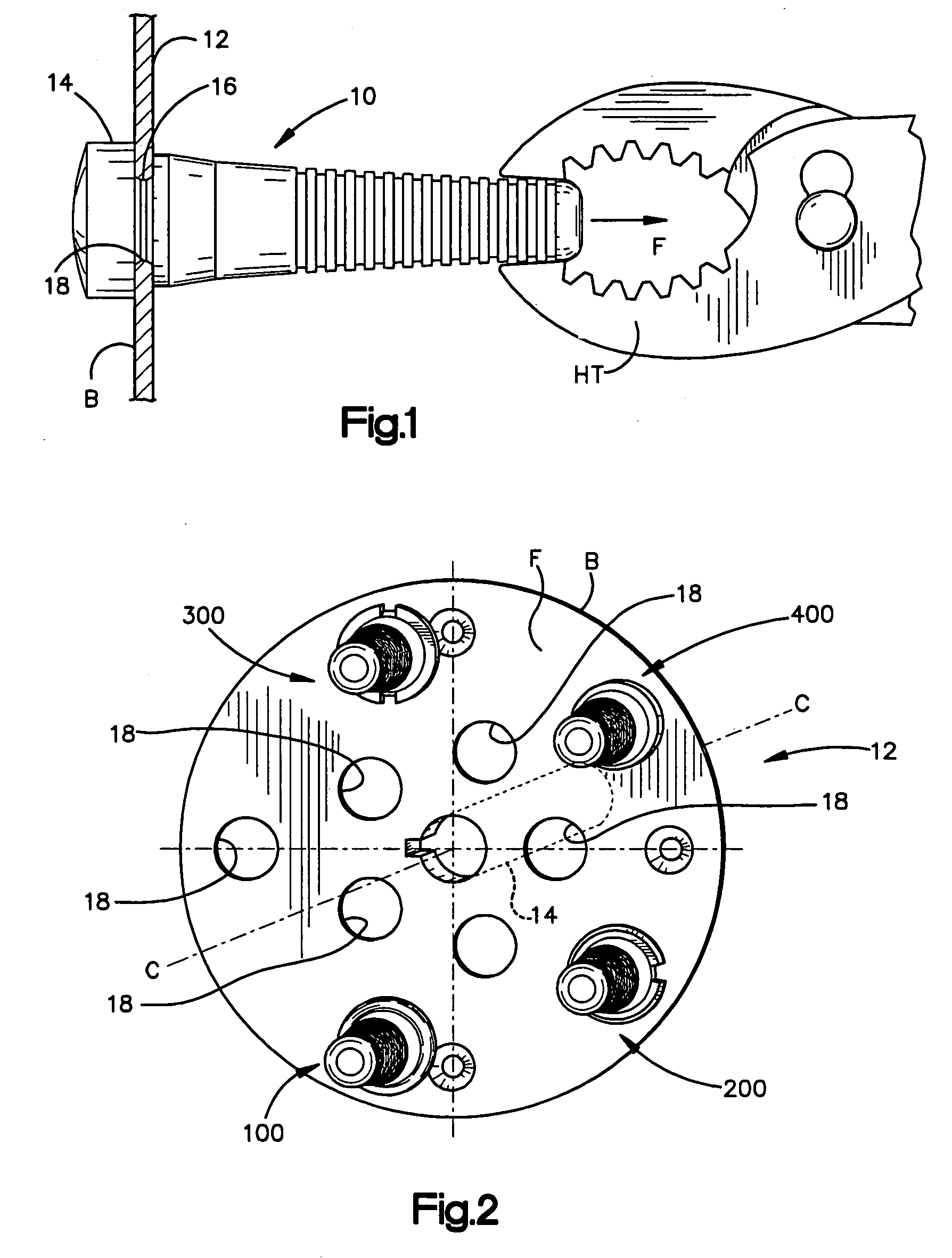
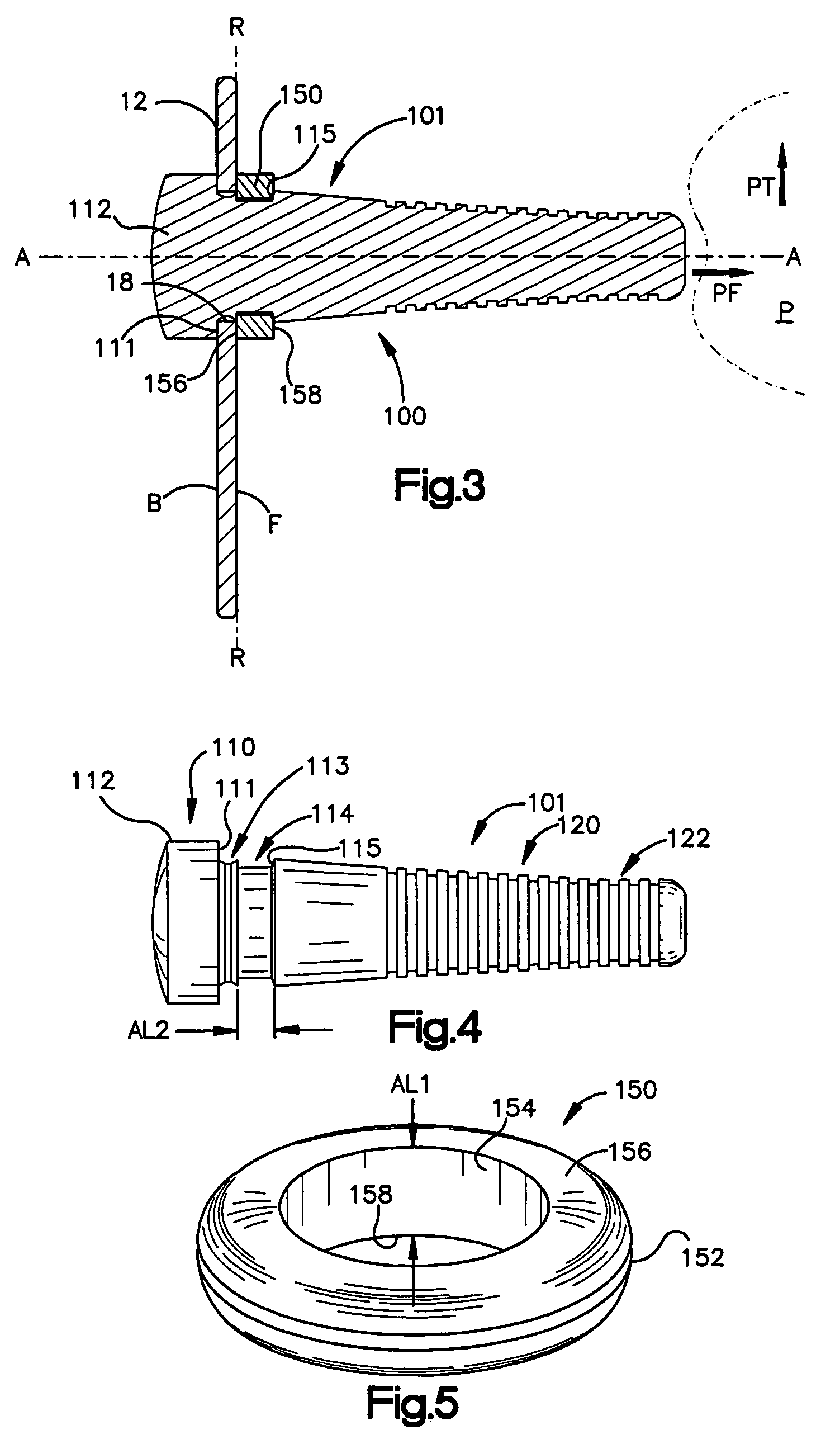
[0046]The first embodiment of the picking finger of the present invention is shown as 100 in FIGS. 3–5. The picking finger 100 includes a picking finger body 101 having a base mounting portion 110 and a tapered, ribbed defeathering portion 120. Preferably, the picking finger body 101 is fabricated from an elastomeric material, for example, a rubber composition, and may advantageously be molded. The picking finger body 100 is inserted from the back side B of the mounting plate 12 with a distal section 122 of the defeathering portion 120 inserted through a circular opening 18 of the mounting plate 12 and pulled from the front side F of the mounting plate 12 in a direction shown as PF in FIG. 3 which is orthogonal to a general extent of the mounting plate 12.

[0047]The distal section 122 of the picking finger body 101 continues to be pulled in the direction PF until a stepped portion 111 of an enlarged end section 112 of the base portion 110 seats a...

second embodiment 200

Second Embodiment 200 of Picking Finger

[0050]The second embodiment of the picking finger of the present invention is shown as 200 in FIGS. 6 and 7. The picking finger 200 is comprised of a picking finger body 201 and includes a base mounting portion 210 and a tapered, ribbed defeathering portion 220. The structure and composition of the picking finger 200 is identical to the picking finger 100 of the first embodiment except for the retaining or fastening component. In the second embodiment, the o-ring 150 of the first embodiment has been replaced by a split retaining ring 250 (best seen in FIG. 7). Preferably, the retaining ring 250 is comprised of metal or plastic. The retaining ring 250 acts as a fastener or retainer to secure the mounting of the picking finger body 201 to the mounting plate12.

[0051]The retaining ring 250 is preferably applied with a retaining ring hand tool, that when actuated, spreads the ring 250 radially outwardly to enlarge an inner diameter 254 of the retain...

third embodiment 300

Third Embodiment 300 of Picking Finger

[0052]The third embodiment of the picking finger of the present invention is shown as 300 in FIGS. 8–12. The picking finger 300 includes a picking finger body 301 having a base mounting portion 310 and a tapered, ribbed defeathering portion 320. The structure and composition of the picking finger 300 is identical to the picking finger 100 of the first embodiment with the exception of the fastener or retainer component. In the third embodiment, the o-ring 150 of the first embodiment has been replaced by a two piece barbed retaining ring 350 (best seen in FIGS. 9–12).

[0053]The retaining ring 350 includes an arcuate first piece 360 and a mating arcuate second piece 370. The arcuate first piece 360 includes a pair of arms 364, 366 extending from a main body portion 362 . As can best be seen in FIG. 11, the arms 364, 366 include barbs 368, 369.

[0054]The arcuate second piece 370 includes a matching pair of openings 374, 376 (FIG. 12) in respective end...


PUM


Abstract

Picking fingers suitable for use in automatic defeathering machines. The picking fingers are suitable for mounting to circular openings in a mounting plate. The picking finger includes an elastomeric picking finger body and a retainer for securing the picking finger to the mounting plate. Three embodiments are disclosed which provide for installation of the picking finger body from a back side of the mounting plate. Each embodiment features a different retainer component. A fourth embodiment is disclosed which provides for installation of the picking finger body from a front side of the mounting plate.

Description

CROSS-REFERENCE TO RELATED APPLICATIONS[0001]This application claims priority from pending U.S. provisional application No. 60 / 553,173, filed Mar. 15, 2004 entitled “Poultry Picking Finger And Mounting Structure”.TECHNICAL FIELD[0002]The present invention relates generally to the field of picking fingers used in automatic defeathering machines for removing feathers from poultry in poultry processing plants and, more specifically, to a picking finger having a mounting structure facilitating secure attachment of picking fingers to a mounting plate and quick and easy replacement of worn / broken picking fingers.BACKGROUND OF THE INVENTION[0003]One task in poultry processing plants is removal of feathers from poultry prior to subsequent processing of the poultry. Automatic defeathering machines have achieved widespread use in removing feathers from poultry. Such defeathering machines include a plurality of picking fingers which are rotated so as to impact the poultry suspended on a convey...

Claims


Application Information

Patent Timeline
Patent Type & Authority Patents(United States)
IPC IPC(8): A22C21/02
CPCA22C21/022
Inventor RAPP, GEOFFREY D.WHITED, JEFFREY A.
Owner BETTCHER INDUSTRIES
Why Eureka
Try Eureka