Hydromechanical transmission

a technology of mechanical transmission and transmission shaft, applied in the direction of fluid gearing, belt/chain/gearing, belt/chain/gearing, etc., can solve the problems of high cost and gear change shock, and achieve the effects of small displacement volume, large speed reduction ratio, and high output for

Inactive Publication Date: 2006-07-04
KOMATSU LTD
View PDF5 Cites 33 Cited by
  • Summary
  • Abstract
  • Description
  • Claims
  • Application Information

AI Technical Summary

Benefits of technology

The patent text describes a hydromechanical transmission system that includes a speed reducer and a second variable displacement hydraulic motor. This system allows for a high output force to be obtained using a compact hydraulic motor and a small displacement volume. The second hydraulic motor is set to have a zero displacement volume at its allowable rotational speed and is cut off from the output shaft with a clutch to prevent the rotational speed from rising to a higher level. The system also includes normal and reverse rotation clutches placed between the planetary gear speed reducer and the first variable displacement hydraulic motor, and a two-way variable displacement hydraulic pump. These features reduce the cost and installation area of the clutches and make the transmission more efficient.

Problems solved by technology

The patent text describes different types of transmissions that can change speed continuously or in steps. However, these methods have drawbacks such as gear change shock or high cost. The technical problem addressed by this patent is to provide a transmission that can change speed smoothly and without causing gear change shock while also being cost-effective.

Method used


Image

  • Hydromechanical transmission
  • Hydromechanical transmission
  • Hydromechanical transmission

Examples


Embodiment Construction

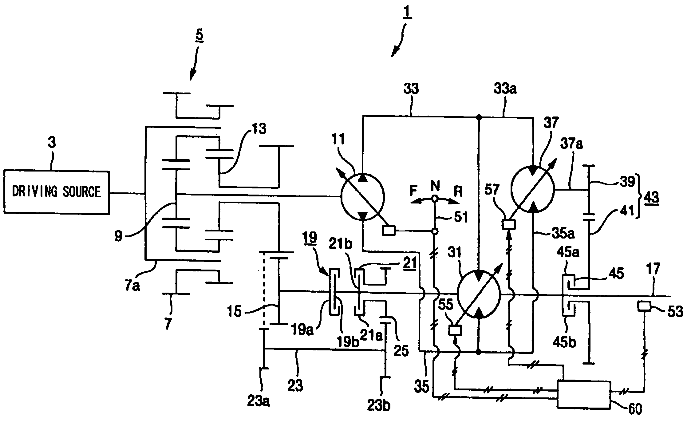
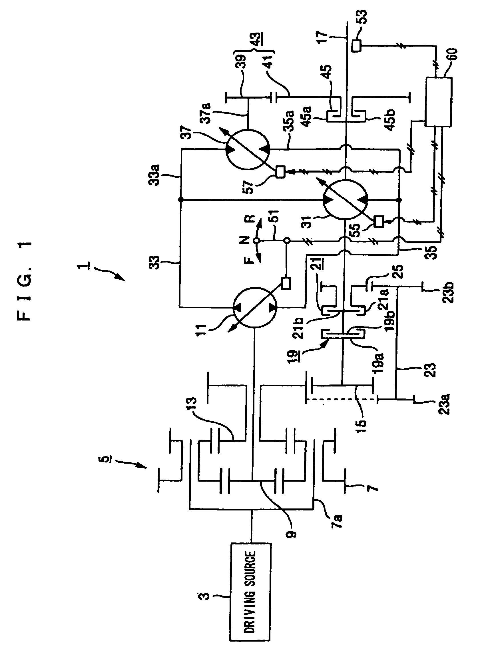
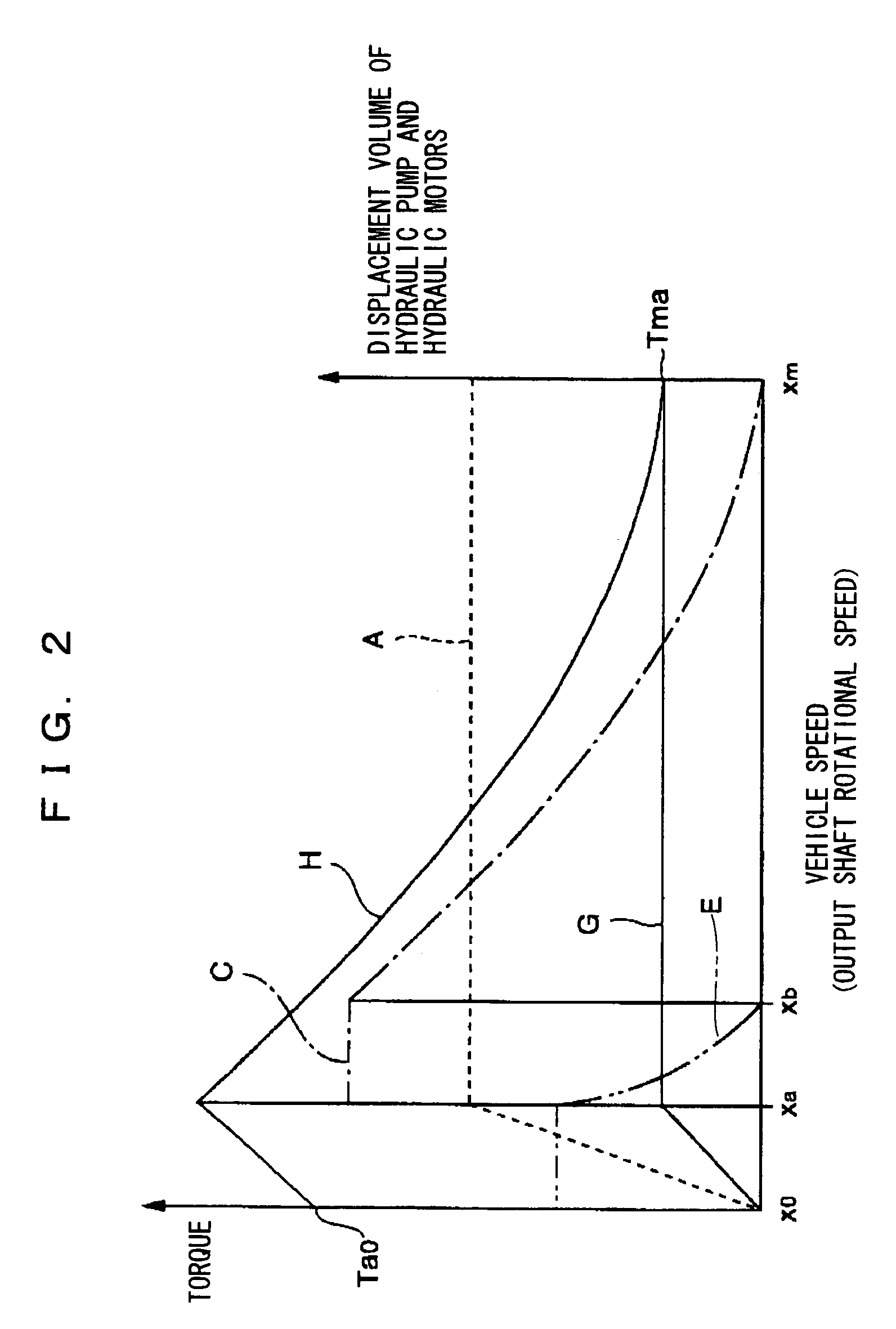
[0012]An embodiment of a hydromechanical transmission according to the present invention will be explained with reference to the drawings, hereinafter. First, the hydromechanical transmission of the embodiment will be explained with use of FIG. 1 to FIG. 3. FIG. 2 shows a vehicle speed, which is a rotational speed of an output shaft, in the horizontal axis, and output torque in the vertical axis. FIG. 3 shows the vehicle speed, which is the rotational speed of the output shaft, in the horizontal axis, and a rotational speed of a hydraulic pump or hydraulic motors in the vertical axis.

[0013]In FIG. 1, in a hydromechanical transmission 1, a driving source 3 such as an engine is connected to a planetary gear 7 via a planetary carrier 7a of a planetary gear speed reducer 5 (hereinafter, called a planetary speed reducer 5), a hydraulic pump 11 is connected to a first sun gear 9, and further, an output shaft 17 is connected to a second sun gear 13 via a normal rotation gear 15. Thereby, o...


PUM


Abstract

A hydromechanical transmission having a continuously variable transmission function and occupying a small area for installation is provided. For this purpose, the transmission includes a driving source (3), a planetary gear speed reducer (5) connected to the driving source, a variable displacement hydraulic pump (11), which is connected to the planetary gear speed reducer, and to which one part of an output force of the driving source is outputted, an output shaft (717), which is connected to the planetary gear speed reducer, and to which the other part of the output force of the driving source is outputted, a first and a second variable displacement hydraulic motors (31, 37) receiving pressure oil from the hydraulic pump and outputting a driving force to the output shaft, and a clutch (45) placed between the second hydraulic motor (37) and the output shaft.

Description


Claims


Application Information

Patent Timeline
Owner KOMATSU LTD
Why Eureka
Try Eureka