Protector for sewer system inlet

a sewer system and inlet technology, applied in gravity filters, water/sludge/sewage treatment, loose filtering material filters, etc., can solve the problems of large quantities of polluting contaminants being washed into sewer systems, large quantities of mud and other contaminants being carried by vehicles, and high production costs

Inactive Publication Date: 2006-07-04
BMP SUPPLIES
View PDF9 Cites 44 Cited by
  • Summary
  • Abstract
  • Description
  • Claims
  • Application Information

AI Technical Summary

Benefits of technology

The invention is about a device used to protect septic systems from pollutants like oily substances and sediment. It consists of a cover with a hollow tube attached to the edge of the septic tank's openings. This prevents harmful materials from entering the septic tank and causing damage. The device has holes that allow water to pass through but keep out unwanted particles.

Problems solved by technology

The technical problem addressed in this patent text relates to finding a cost-effective and safe way to prevent pollutants from entering sewer systems during construction projects without being affected by weather conditions such as rain or snow. Existing solutions like bag filters can be expensive, difficult to install, and potentially unsafe, while others designed for overhead use may also have limitations including difficulty handling excess water and vulnerability to damage from heavy machinery.

Method used


Image

  • Protector for sewer system inlet
  • Protector for sewer system inlet
  • Protector for sewer system inlet

Examples


Embodiment Construction

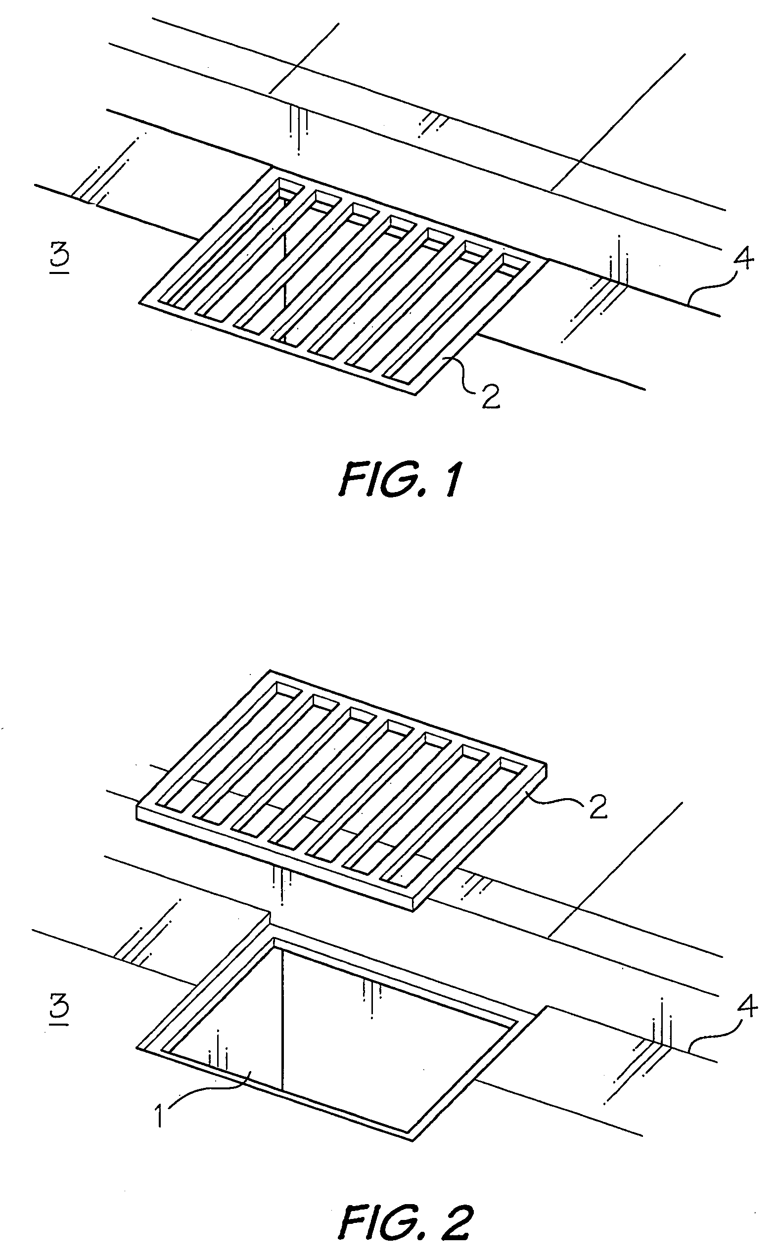
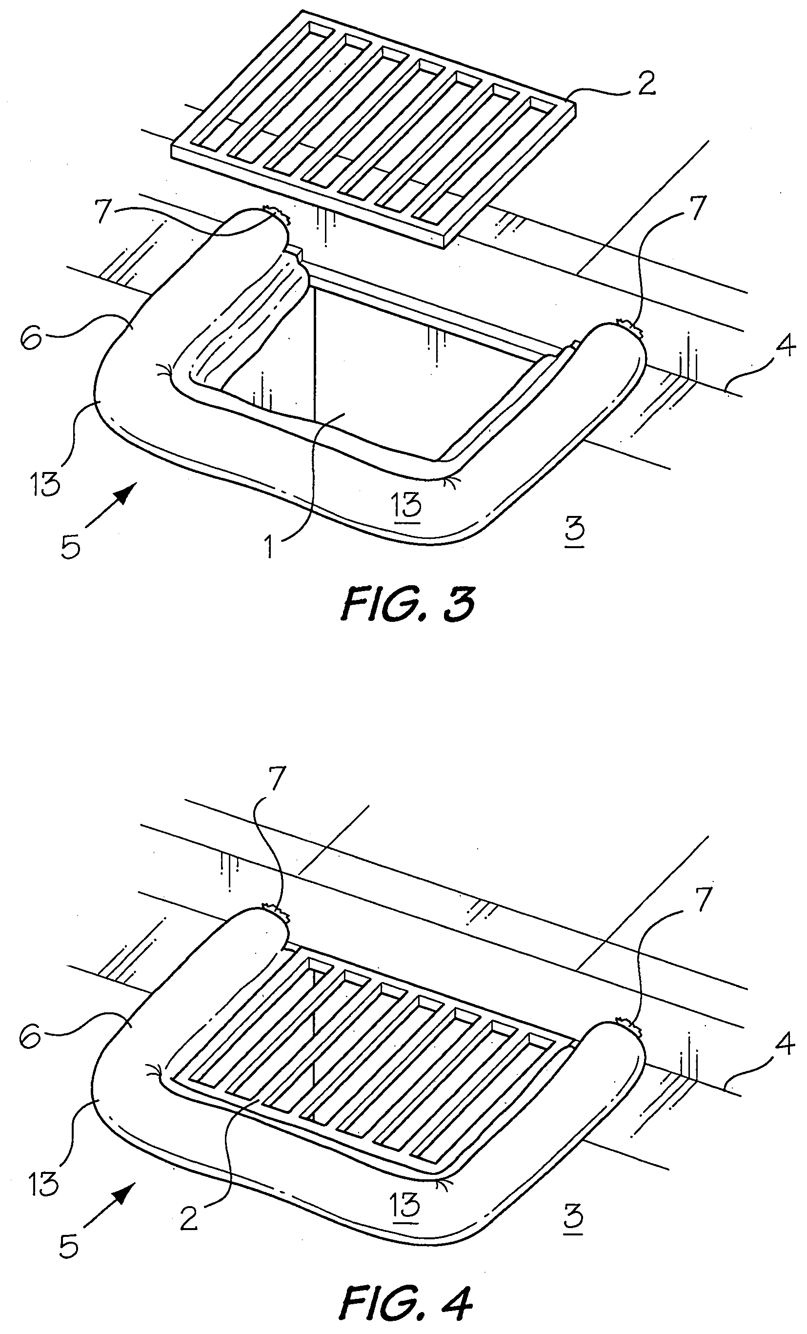
[0018]Referring to FIGS. 1 and 2, the protector of the present invention is intended for use in preventing the flow of contaminants into the opening or inlet 1 into a sewer system which is normally closed by a metal grate 2. Usually, such inlets are located on the side of a roadway 3 adjacent to or overlapping a curb 4. In order to install the protector of the present invention, the grate 2 is lifted from the sewer inlet 1 (FIGS. 2 and 3).

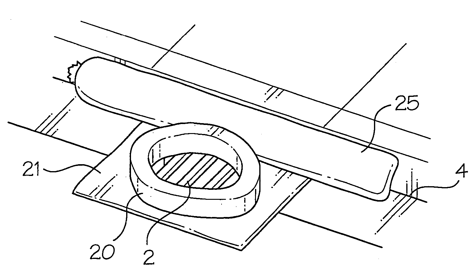
[0019]As shown in FIGS. 3 and 4, the protector, which is indicated generally at 5, is defined by a sausage-like tubular casing 6 for placing around the periphery of the sewer opening 1. The casing 6 is formed of a material which is porous to water, but impermeable to oil, tar, gravel, sand and other contaminants. Suitable casing materials include plastics such as polyethylene and polyesters, burlap and tarpaulin. Preferably, the casing 6 is brightly colored, e.g. a bright orange HDPE, so that it is readily visible to vehicle operators. The ends 7 o...


PUM

PropertyMeasurementUnit
Permeabilityaaaaaaaaaa
Impermeabilityaaaaaaaaaa
Compressive stressaaaaaaaaaa

Abstract

A protector for the inlet into a sewer system includes a straight or annular, porous tubular casing for placing on or around the periphery of a sewer grate; a skirt extending inwardly or outwardly from the bottom of the casing for overlapping the side edges of a sewer opening so the grate retains the protector in the use position; and a filler in the casing for maintaining the casing in an expanded condition, at least one of the casing, the skirt and the filler being permeable to water and impermeable to contaminants, whereby water can flow into the system while contaminants are blocked.

Description


Claims


Application Information

Patent Timeline
Owner BMP SUPPLIES
Why Eureka
Try Eureka