Control unit with variable visual indicator

a technology of visual indicators and control units, applied in the field of control units, can solve the problems of difficulty in finding the characters one is seeking, small key size, and difficulty in writing messages with the keypad of the mobile phon

Inactive Publication Date: 2006-07-04
UNITED KEYS
View PDF61 Cites 53 Cited by
  • Summary
  • Abstract
  • Description
  • Claims
  • Application Information

AI Technical Summary

Problems solved by technology

Already with two characters indicated on one key, it may be difficult to find the characters one is seeking, even though it is shown on the key.
As a result thereof, the characters indicated on the key become very small, and it is both difficult and time-consuming to write messages with the key pad of the mobile phone.
Similar problems exist for most non-stationary control units.
One problem is that the aim of making the control units small and flexible to use, in some cases becomes the clean contrary to the aim of designing a control unit which is able to emit a large number of different control signals, whereby the manufacturers often have to compromise.
Another problem related to data input means having visual indicators is that it is predefined during manufacturing which indicators are devised on each key, rotary control, etc.
However, a reconfigured keyboard becomes difficult to master since the indications on the keys remain unchanged.
One inconvenience with the presented solution is however that the feeling of working with separates keys is lost, at which one must be very accurate to guarantee that the fingers do not glide out of the desired finguring.
Another inconvenience is that the input screen must be of a touch-screen type, which is considerably less robust than traditional keys.

Method used


Image

  • Control unit with variable visual indicator
  • Control unit with variable visual indicator
  • Control unit with variable visual indicator

Examples


Embodiment Construction

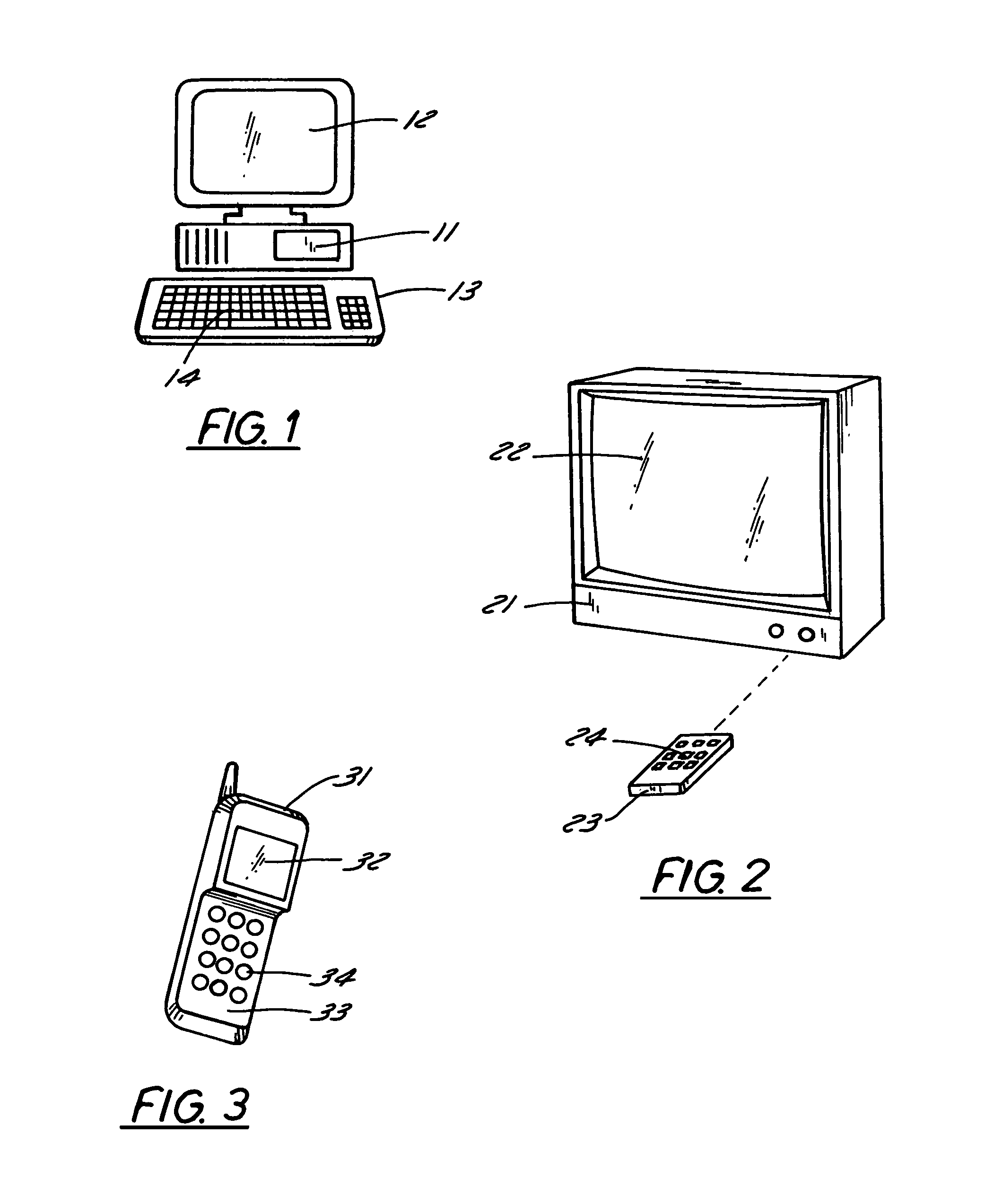
[0022]In the FIGS. 1 through 3, examples of devices are outlined for which the present invention is of use and advantageous. In FIG. 1, a computer 11 is schematically illustrated, which is equipped with a presentation unit 12 in the shape of a screen. Keyboard 13 is arranged as a user interface, which keyboard serves as a control unit for the computer. Further, the keyboard is arranged in a known manner with a plurality of data input means in the shape of keys 14. The user gives control data to the keyboard by means of the keys and control signals are thereby transmitted from the keyboard in the figure, to the computer. Said communication connection could be wire dependent or wireless. In the computer there is an interpreting means comprising a computer program devised to decode the control signals, so as to interpret which action or measures the user has ordered.

[0023]FIG. 2 schematically illustrates a TV-set 21 that is equipped with a presentation unit 22 in the shape of a picture...


PUM


Abstract

A system for controlling an apparatus (11, 21, 31), which system comprises a control unit (13, 23, 33) adapted to transfer control signals to the apparatus dependent on the control data. Said control unit comprises data input means (14, 24, 34, 44) to input said control data, and said apparatus comprises interpreting means adapted to translate said control signal into an action. Aiming to indicate for a user of the control unit, which action the apparatus is arranged to take when activating the data input means, a visual indicator is arranged on said data input means. The invention is characterized in that said data input means comprises a variable presentation means (45, 57), arranged to realise said indicator, wherein said control unit comprises a first storage means (53) adapted to store the visual data presentable with said presentation unit. Preferably, said control unit comprises several separate data input means, each provided with a presentation means, in which each presentation means comprises separate displays, arranged to present a picture dependent on said visual data.

Description

CROSS REFERENCE TO RELATED APPLICATION[0001]This application is a continuation application of presently copending U.S. application Ser. No. 09 / 690,854, filed Oct. 17, 2000, and entitled “Control Unit with Variable Visual Indicator,” which will issue Sep. 28, 2004, as U.S. Pat. No. 6,798,359.FIELD OF THE INVENTION[0002]The present invention is related to control units arranged with data input means, which control units are devised to transmit control signals dependent on the activation of said data input means. More precisely the invention is related to control units wherein said data input means are devised with variable visual indicators.BACKGROUND[0003]Each day a great number of electronic equipment are used, for which equipment control signals often are needed or wanted. For this purpose specially adapted control units are often used. Examples of such control units are keyboards for computers, remote controls for TV-sets, stereo recorders or other electronic apparatus, key pads o...

Claims


Application Information

Patent Timeline
Patent Type & Authority Patents(United States)
IPC IPC(8): H03M11/00G06F3/147G06F17/30
CPCG06F3/0231G06F3/0238G06F17/30864G06F3/147H01H2219/016G06F16/951
Inventor IVANCIC, VALDI
Owner UNITED KEYS
Why Eureka
Try Eureka