Multiple hinged tray cable connecting joint and method of using same

a technology of connecting joints and hinged trays, which is applied in the direction of fibre mechanical structures, instruments, optical light guides, etc., can solve the problems that fiber optic cables cannot be made and deployed in infinite length

Active Publication Date: 2006-07-04
SUBCOM LLC
View PDF6 Cites 31 Cited by
  • Summary
  • Abstract
  • Description
  • Claims
  • Application Information

AI Technical Summary

Problems solved by technology

Because these fiber optic cables cannot be made and deployed in infinite length, sections of the cables must be attached together to extend across large distances.

Method used


Image

  • Multiple hinged tray cable connecting joint and method of using same
  • Multiple hinged tray cable connecting joint and method of using same
  • Multiple hinged tray cable connecting joint and method of using same

Examples


Embodiment Construction

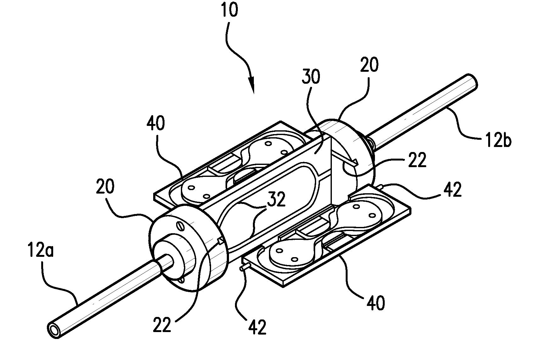
[0017]Referring to FIG. 1, a multiple hinged tray cable connecting joint 10 is shown between two fiber optic cables 12a, 12b. Although the exemplary embodiment of the multiple hinged tray cable connecting joint 10 is designed for use with an undersea fiber optic cable, the present invention can also be used with terrestrial cables.

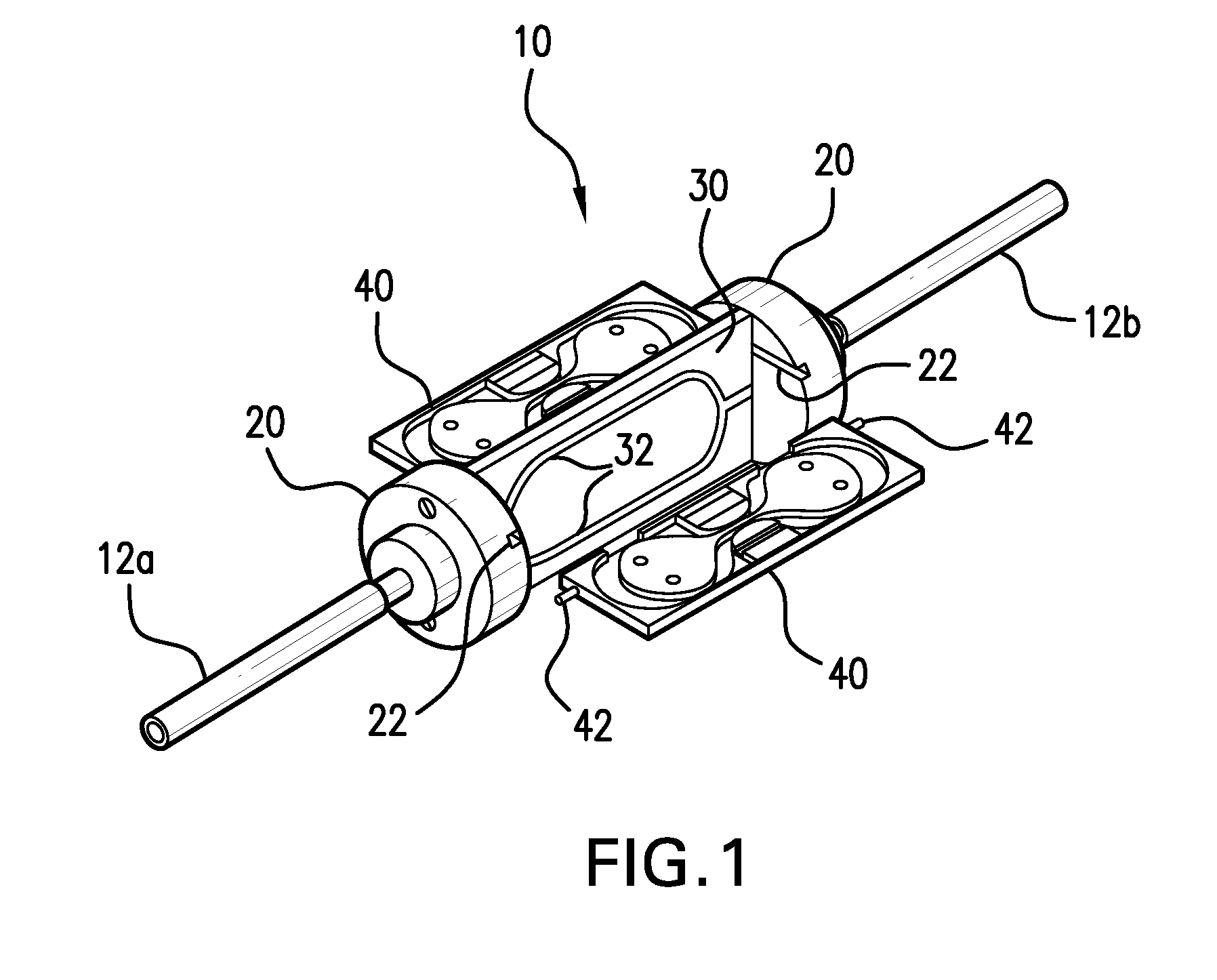
[0018]According to one embodiment, the connecting joint 10 comprises first and second sockets 20 coupled to the respective cables 12a, 12b, a shelf 30 connected between the sockets 20, and fiber trays 40 pivotably coupled between the sockets 20. Each of the sockets 20 includes slots 22 for receiving pivot pins 42 on the fiber trays 40 to allow the fiber trays 40 to pivot within the connecting joint 10. The shelf 30 may include fiber-receiving grooves 32 for receiving the fibers as they pass from the cables 12a, 12b to the fiber trays 40. Although the exemplary embodiment shows the slots 22 and grooves 32 with a specific shape and configuration, those skill...


PUM


Abstract

A multiple hinged tray cable connecting joint includes a plurality of fiber trays pivotably coupled between sockets connected to fiber optic cables. The fiber trays can be positioned in a fiber loading position in which the fiber is spliced and coiled into the tray. The fiber trays can then be pivoted to a fiber storage position.

Description

TECHNICAL FIELD[0001]The present invention relates to fiber optic cable connecting joints and more particularly, to a cable connecting joint having hinged fiber trays.BACKGROUND INFORMATION[0002]Fiber optic cables are deployed across long distances (e.g., many miles of ocean) to establish communication networks. Because these fiber optic cables cannot be made and deployed in infinite length, sections of the cables must be attached together to extend across large distances. Cable joints are used to connect the tails of fiber optic cables together, for example, when splicing the optical fibers within the cables.[0003]Undersea fiber optic cable connecting joints are designed to transfer tension and torque between the strength members of the two cable tails being connected and to provide electrical continuity between the power conductors of the two cable tails. Cable connecting joints also provide optical continuity between the fiber optics of the two cable tails and provide storage of ...

Claims


Application Information

Patent Timeline
Patent Type & Authority Patents(United States)
IPC IPC(8): G02B6/00
CPCG02B6/4447G02B6/4455
Inventor GIORDANO, DAVID A.KORDAHI, MAURICEGIRZONE, WILLIAM EDMUND
Owner SUBCOM LLC
Why Eureka
Try Eureka