Multi-band antenna and notebook computer with built-in multi-band antenna

a multi-band antenna and notebook computer technology, applied in the direction of resonant antennas, portable computer details, instruments, etc., can solve the problems of inability to communicate with electronic equipment with the built-in antenna in an area where the designed frequency band is located, inconvenient design restrictions, and high risk of antenna damage, etc., to achieve convenient radio frequency communication, prevent damage, and wide area

Inactive Publication Date: 2006-07-04
LG ELECTRONICS INC
View PDF34 Cites 42 Cited by
  • Summary
  • Abstract
  • Description
  • Claims
  • Application Information

AI Technical Summary

Benefits of technology

[0018]With the multi-band antenna and the notebook computer with a built-in multi-band antenna of the present invention, the antenna is installed at both inner sides of the display device so that when a user stands the display device to use the notebook computer the antenna is stood together with the display device, comparatively high, and thus, radio frequency communication is easy and the antenna is prevented from being damaged by being caught by a human or an object.
[0019]With the notebook computer with a built-in antenna in the present invention, since the grounding unit is inserted between the liquid crystal frame and the bracket to extend the grounding over a comparatively wide area, so as to make a stable r

Problems solved by technology

But, notably, there are inconvenient aspects and restrictions in designing such an antenna and in its adaptation to the mobile electronic equipment due to the special requirement that it be mounted for use in a compact mobile electronic equipment.
This type of antenna has a high risk that it could be easily damaged as a user inadvertently covers the display device after the antenna is stood vertically for use.

Method used


Image

  • Multi-band antenna and notebook computer with built-in multi-band antenna
  • Multi-band antenna and notebook computer with built-in multi-band antenna
  • Multi-band antenna and notebook computer with built-in multi-band antenna

Examples


Embodiment Construction

[0035]Reference will now be made in detail to the preferred embodiments of the present invention, examples of which are illustrated in the accompanying drawings.

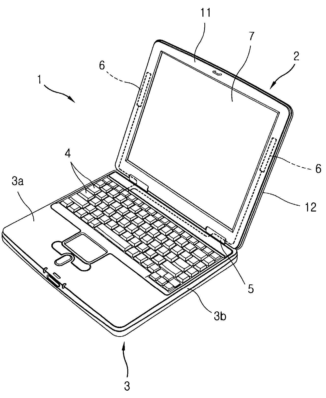
[0036]FIG. 1 is a perspective view showing a notebook computer with a multi-band antenna in accordance with the present invention.

[0037]A mobile electronic equipment 1 with an antenna 6 includes a notebook computer, a laptop computer, a palmtop computer, or the like. A main body 3 is formed as an up-case 3a and a down-case 3b are coupled. A keyboard 4 having a plurality of keys for inputting data is installed at an upper surface of the up-case 3a. A PCB is installed inside the down-case 3b, which various modules such as an optical disk drive, a hard disk drive or the like are connected to and mounted on. A LAN card (not shown) enabling a radio frequency communication is provided at one side of the PCB.

[0038]At a rear end portion of the upper surface of the main body 3, there is provided a display device 2 is rotatably instal...


PUM


Abstract

A multi-band antenna and a notebook computer with a built-in multi-band antenna are disclosed. Since the multi-band antenna is installed at the inner side of a upper and a lower case, it is much favored for a radio communication when a computer is in use by standing up a display device. The multi-band antenna includes at least two transmitting and receiving parts formed with different lengths to fit frequency bands, so that a remote communication of at least two or more bands can be made. The multi-band antenna is positioned between liquid crystal and a side wall of the lower case, and a grounding unit is installed to contact a liquid crystal frame. That is, since the grounding unit is grounded to the liquid crystal frame and the bracket, substantially, the liquid crystal frame and the bracket are wholly grounded to ensure a stable radio frequency communication.

Description

[0001]This application is a continuation-in-part of application Ser. No. 10 / 036,545 filed Jan. 7, 2002 now U.S. Pat. No. 6,957,085, which claims priority to Korean Application Serial Nos. 19281 / 2001 filed Apr. 11, 2001 and 33952 / 2001 filed Jun. 15, 2001, the entire disclosure of each is incorporated herein by reference.BACKGROUND OF THE INVENTION[0002]1. Field of the Invention[0003]The present invention relates to a multi-band antenna and a notebook computer with a built-in multi-band antenna and, more particularly, to a notebook computer in which a multi-band antenna is installed at the inner side of a corner portion of a display device, not being damaged by an external impact or not causing an inconvenience in use, and several transmitting and receiving parts are formed at the antenna to correspond to multi-band radio frequency transmission and reception.[0004]2. Description of the Background Art[0005]A mobile electronic equipment is operated by power supplied from a small portabl...

Claims


Application Information

Patent Timeline
IPC IPC(8): H04M1/00H04B1/38G06F1/16H01Q1/22
CPCG06F1/1616G06F1/1637H01Q1/2266H01Q1/22G06F1/1698
Inventor SHIN, HYO SIKBANG, KWANG SEOGKIM, EUNG BOK
Owner LG ELECTRONICS INC
Why Eureka
Try Eureka