Method for minimizing RAID 0 data transfer rate variability

Active Publication Date: 2006-07-04
AVAGO TECH INT SALES PTE LTD
View PDF7 Cites 3 Cited by
  • Summary
  • Abstract
  • Description
  • Claims
  • Application Information

AI Technical Summary

Benefits of technology

[0012]The advantages of the present invention are that the data transfer rate of a RAID 0 stripe is maximized. When the RAID 0 array is constructed with half of the disk drives wri

Problems solved by technology

Hard disk storage devices have certain inherent variability in data transfers due to the geometry of the disk platter.
The perfo

Method used


Image

  • Method for minimizing RAID 0 data transfer rate variability
  • Method for minimizing RAID 0 data transfer rate variability
  • Method for minimizing RAID 0 data transfer rate variability

Examples


embodiment 100

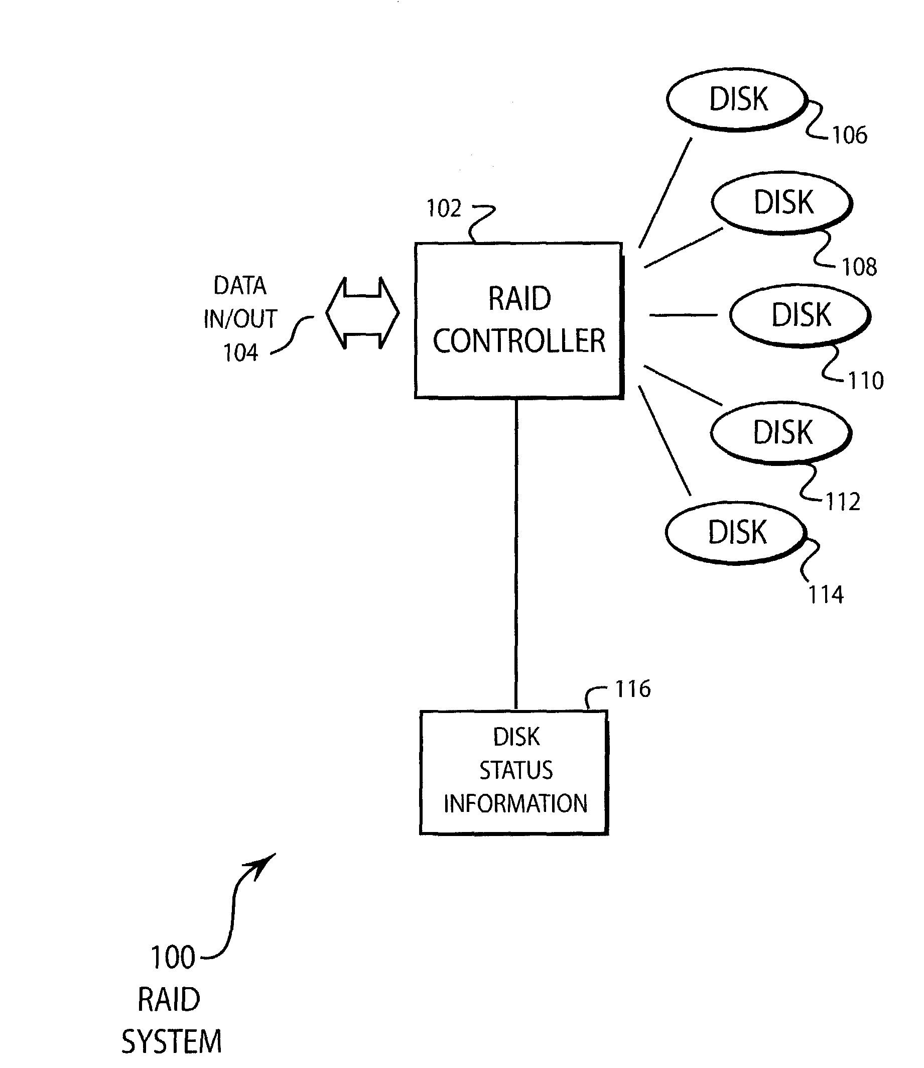
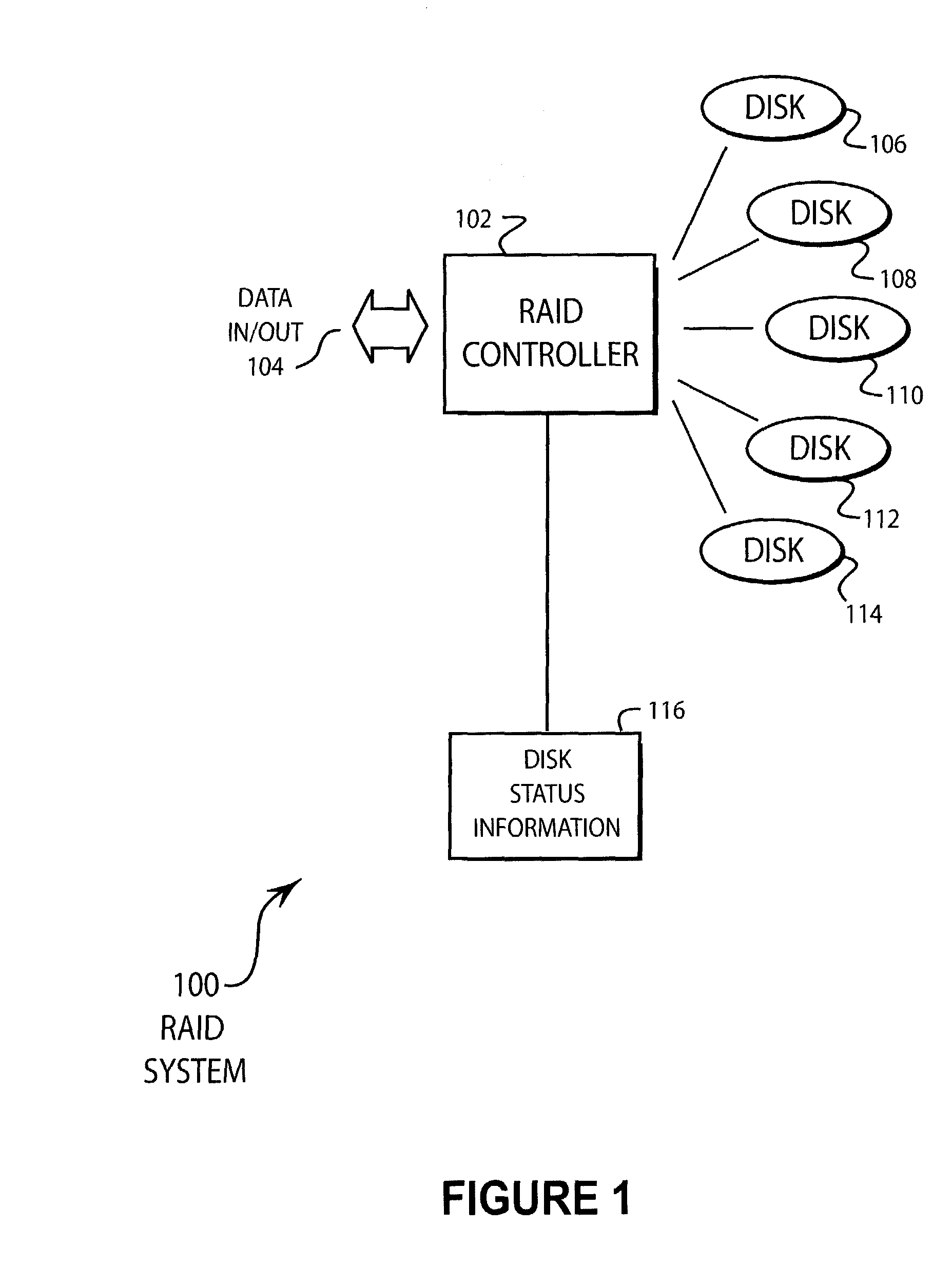
[0017]FIG. 1 illustrates an embodiment 100 of the present invention of a RAID system. A RAID controller 102 receives and sends data 104. The RAID controller 102 controls disks 106, 108, 110, 112, and 114. The RAID controller 102 may maintain the disk status information 116.

[0018]As is common practice in RAID 0 systems, the data that is received is divided amongst the various disk drives and simultaneously written to all of the disk drives. By writing a portion of the data to each drive simultaneously, the maximum data transfer rate of the system is approximately equal to the data transfer rate of the individual disk drives multiplied by the number of disk drives. The data that is written to all of the disk drives is known as a data slice.

[0019]The disk drives 106, 108, 110, 112, and 114 have the characteristic that the data transfer rate varies based on the track location to which the drive writes. When writing to tracks near the outside of the disk, the data transfer rate is relati...

embodiment 200

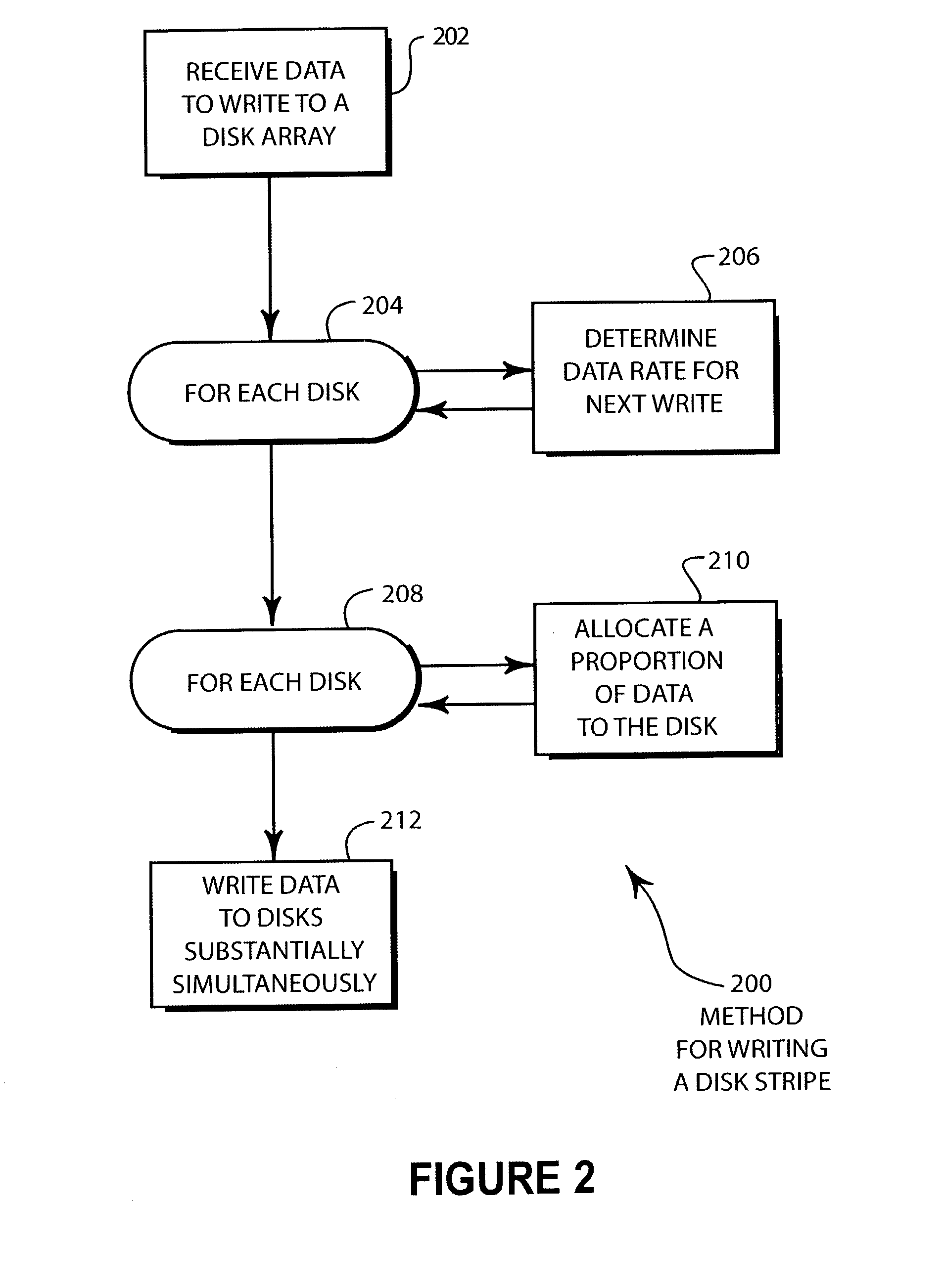
[0024]FIG. 2 illustrates an embodiment 200 of a method for writing a disk stripe. The data is received by the RAID controller in block 202. For each disk in block 204, the data rate is determined for the next write operation in block 206. For each disk in block 208, a proportion of the data is allocated to each disk in block 210. The data is written to the drives substantially simultaneously in block 212.

[0025]The data rate for each disk drive in block 204 may be determined by calculating the approximate data rate based on the track number that will be used by the disk drive. A track number pointer may be stored in the controller memory and referenced for the operation of block 206. The data transfer rates for each disk drive may be a gross approximation or may be a very precise measurement.

[0026]In other embodiments, the data rate for each disk drive in block 206 may be determined by querying each disk drive individually. The drives may perform a short write operation to test the a...

embodiment 300

[0029]FIG. 3 Illustrates an embodiment 300 of the present Invention of a RAID 0 system with staggered tracks. Disks 302, 308, and 310 are arranged such that the first tracks that are written are outside tracks 312, 316, and 320. Disks 304 and 308 are arranged such that the first tracks that are written are inside tracks 314 and 318.

[0030]The embodiment 300 when used in conjunction with the method 200 illustrated in FIG. 2 may result in a RAID 0 system with reduced variability in data transfer rate. Further, the lowest data transfer rate may be substantially higher than if the embodiment were configured to write to the same tracks of each disk drive.

[0031]Using the example illustrated in the discussion of FIG. 1, disks 302, 306, and 310 may be able to write at 200 KB / sec while disks 304 and 308 may be able to write at 100 KB / sec. By allocating an 800 KB stripe as 200 KB to each of disks 302, 306, and 310 and 100 KB each to disks 304 and 308, an overall data transfer rate of 800 KB / se...


PUM


Abstract

A RAID 0 disk array has an optimizing algorithm for allocating the amount of data stored to each drive in a disk array. The algorithm allocates a proportion of the data for each stripe to the various disk drives based at least in part on the data transfer rate for each drive. The disk array may be constructed such that about half of the disk drives write to the outside tracks of the drives while the remaining disks write to the inside tracks. Using the algorithm, the minimum data transfer rate for the disk array may be maximized.

Description

BACKGROUND OF THE INVENTION[0001]a. Field of the Invention[0002]The present invention pertains to computer memory storage devices and specifically to storage devices using RAID 0 architecture.[0003]b. Description of the Background[0004]Hard disk storage devices have certain inherent variability in data transfers due to the geometry of the disk platter. On tracks near the outside of the disk, data transfer rates may be much higher than data transfer rates for tracks on the inside. This is due to the fact that the speed with which the heads ride over the disk changes in proportion to the radius of the track location.[0005]In a RAID 0 disk array, several disk drives are operated in parallel. When a data block is written to the array, the data may be written in ‘stripes’ wherein the data is divided among the various disk drives and written substantially simultaneously.[0006]The performance of a RAID 0 array may be adversely affected by the data transfer rates of the various disk drives ...

Claims


Application Information

Patent Timeline
IPC IPC(8): G06F12/00G06F3/06
CPCG06F3/061G06F3/0689G06F3/0638G06F3/0653
Inventor FURE, JAN
Owner AVAGO TECH INT SALES PTE LTD
Why Eureka
Try Eureka