
Electronic device comprising antenna

a technology of electronic devices and antennas, applied in the direction of resonant antennas, substantially flat resonant elements, transportation and packaging, etc., can solve the problems of wind noise and exterior damage of vehicles, and achieve the effect of maximizing data transmission rate, reducing electromagnetic mutual coupling, and efficient installation in vehicles

Active Publication Date: 2019-09-10
SAMSUNG ELECTRONICS CO LTD
View PDF38 Cites 0 Cited by
  • Summary
  • Abstract
  • Description
  • Claims
  • Application Information

AI Technical Summary

Benefits of technology

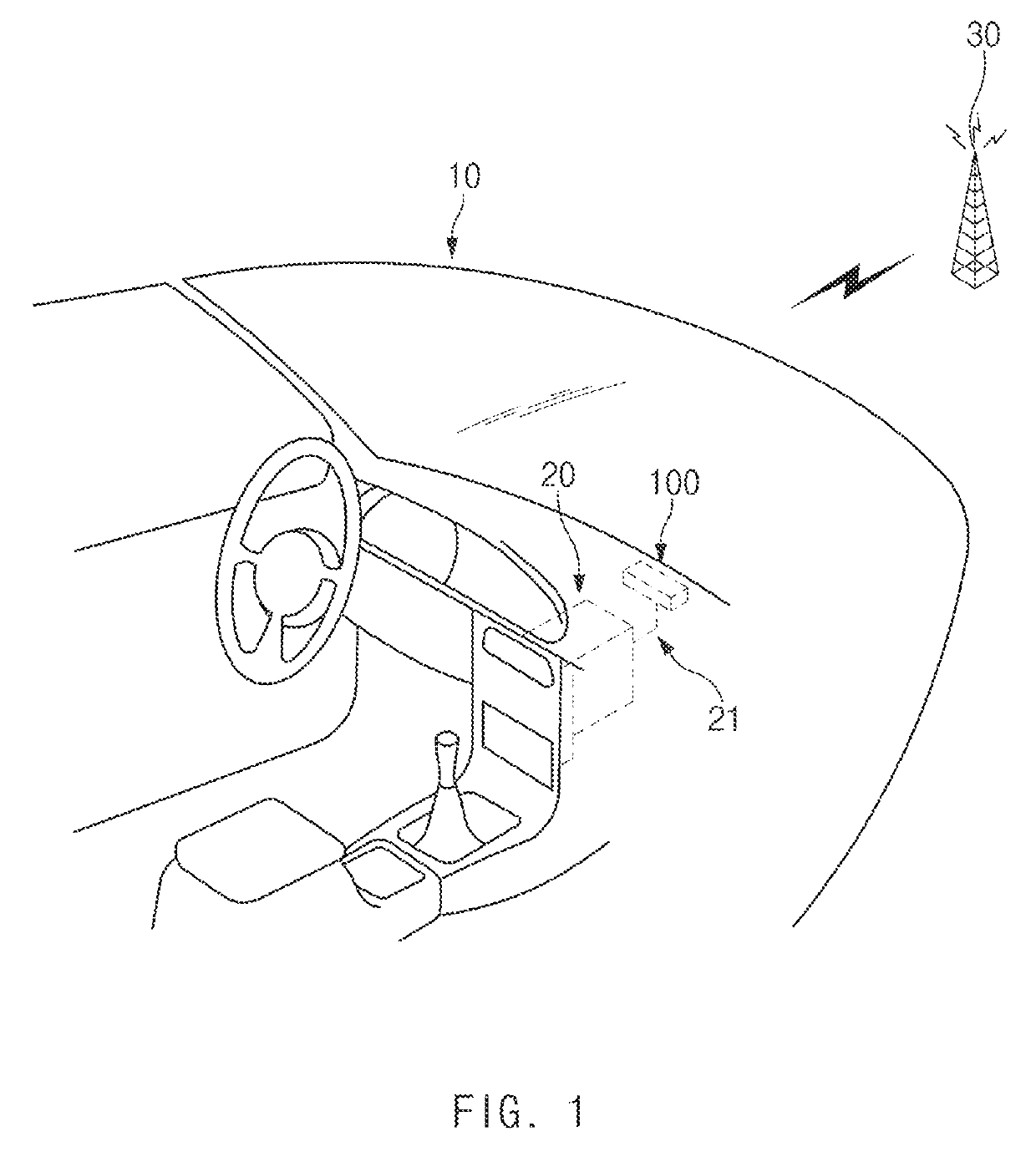
[0006]Aspects of the disclosure are to address at least the above-mentioned problems and / or disadvantages and to provide at least the advantages described below. Accordingly, an aspect of the disclosure is to provide an integrated antenna module capable of being efficiently installed in a vehicle by integrating antennas supporting various bands within a specific space.
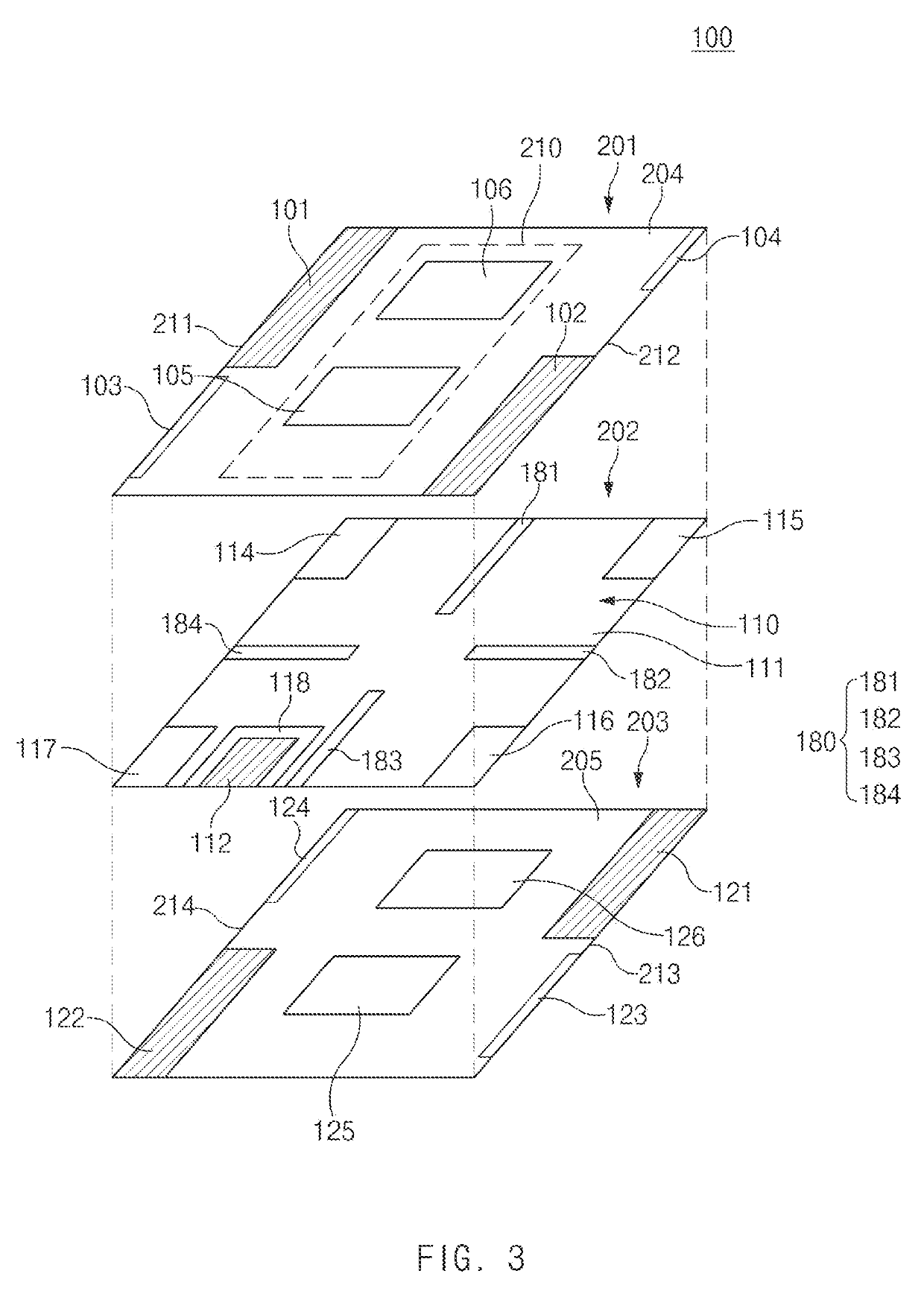
[0007]Another aspect of the disclosure is to provide an integrated antenna module that employs an antenna supporting multi input multi output (MIMO) communication to maximize data transmission rate and effectively arranges a multi-band antenna to reduce electromagnetic mutual coupling between antennas and to have the improved isolation performance.
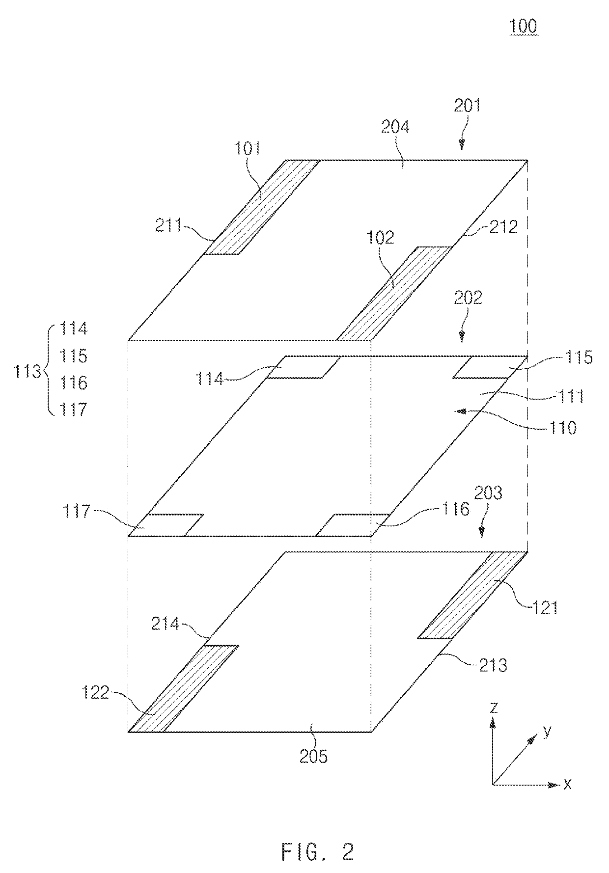
[0012]According to various embodiments of the disclosure, it is possible to effectively arrange a multi-band antenna in a limited space through a plurality of conductive patterns, which is positioned in a diagonal direction in at least one plane.

Problems solved by technology

Since being exposed to the outside, an antenna for a vehicle such as shark fin antenna may deface the exterior of a vehicle and may be damaged by an external environment according to the related art.
Also, when the vehicle drives at a high speed, a wind noise may occur.

Method used


Image

  • Electronic device comprising antenna
  • Electronic device comprising antenna
  • Electronic device comprising antenna

Examples


Embodiment Construction

[0051]The following description with reference to accompanying drawings is provided to assist in a comprehensive understanding of various embodiments of the disclosure as defined by the claims and their equivalents. It includes various specific details to assist in that understanding but these are to be regarded as merely exemplary. Accordingly, those of ordinary skill in the art will recognize that various changes and modifications of the various embodiments described herein can be variously made without departing from the scope and spirit of the disclosure. In addition, descriptions of well-known functions and constructions may be omitted for clarity and conciseness.

[0052]The terms and words used in the following description and claims are not limited to the bibliographical meanings, but, are merely used by the inventor to enable a clear and consistent understanding of the disclosure. Accordingly, it should be apparent to those skilled in the art that the following description of ...


PUM


Abstract

An antenna assembly in a vehicle is provided. The antenna assembly includes a first plane including a first edge and a second edge extending in parallel to each other in a first direction, a second plane spaced apart from the first plane that overlaps the first plane and including a third edge extending along the first edge, and a fourth edge extending along the second edge, a non-conductive layer interposed between the first plane and the second plane, and a plurality of wireless communication circuits electrically connected to the antenna assembly, wherein the first conductive pattern and the second conductive pattern are positioned diagonally at opposing corners with each other when viewed from above the first plane, and wherein the third conductive pattern and the fourth conductive pattern are positioned diagonally against each other without overlapping with the first and second conductive patterns, when viewed from above the first plane.

Description

CROSS-REFERENCE TO RELATED APPLICATION(S)[0001]This application is based on and claims priority under 35 U.S.C. § 119(a) of a Korean patent application number 10-2017-0076585, filed on Jun. 16, 2017, in the Korean Intellectual Property Office, the disclosure of which is incorporated by reference herein its entirety.BACKGROUND1. Field[0002]The disclosure relates to a technology for implementing the antenna of an electronic device.2. Description of Related Art[0003]Wireless communication technology makes it possible to transmit and receive various forms of information such as a text, an image, a video, voice, and the like. With the advent of autonomous vehicles, an automotive communication technology for continuously communicating with road infrastructure and other vehicles and for exchanging or sharing various pieces of useful information such as a traffic condition or the like has been recently developed. For example, a shark fin antenna supporting one or more communication protocol...

Claims


Application Information

Patent Timeline
Patent Type & Authority Patents(United States)
IPC IPC(8): H01Q1/24H01Q7/00H01Q1/52H01Q9/04H04B1/40H04W4/40H01Q13/10H01Q21/28H01Q1/48H01Q1/32H01Q1/38
CPCH01Q1/38H01Q1/243H01Q1/32H01Q1/48H01Q1/521H01Q13/10H01Q21/28H04B1/40H01Q9/0407H04W4/40H01Q7/00H01Q5/10H01Q5/307H01Q5/50H01Q23/00H01Q1/3275H04B1/3822
Inventor SUNG, SANG BONGKIM, SE WOONGYUN, SU MINKANG, WOO SUKLEE, IN YOUNG
Owner SAMSUNG ELECTRONICS CO LTD
Learn More