

Ultra-compacted microstrip patch array antenna
A technology of microstrip patch and array antenna, which is applied in the directions of antenna, antenna coupling, antenna array, etc., can solve the problems of poor unit isolation and large size of array antenna, and achieve the effect of improving isolation
- Summary
- Abstract
- Description
- Claims
- Application Information
AI Technical Summary
Problems solved by technology
Method used
Image

Examples
Embodiment Construction
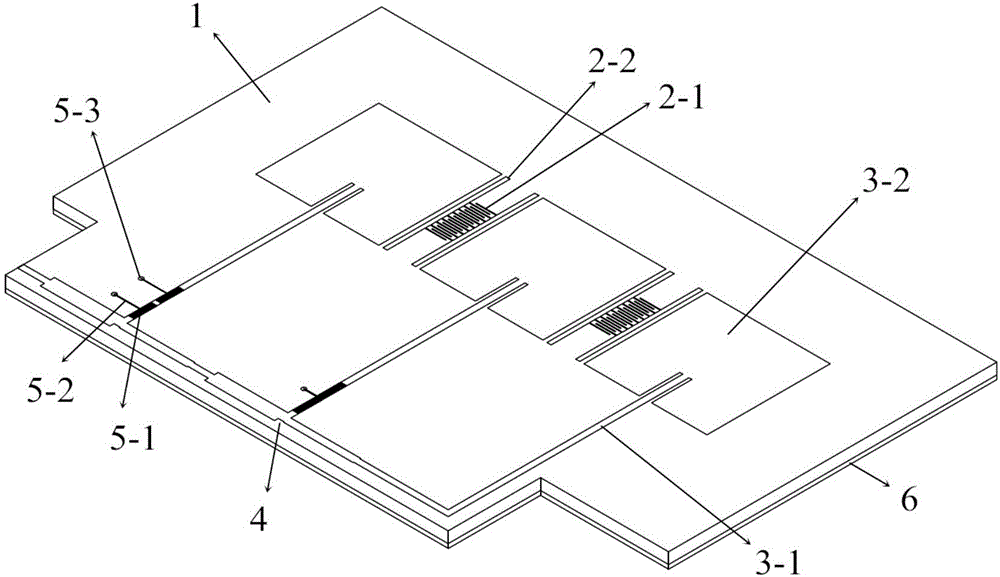
[0026] An ultra-compact microstrip patch array antenna, such as figure 1 As shown, it consists of a dielectric board 1, an antenna array, a metal floor 6, a decoupling network and a feed network.
[0027] The dielectric board 1 serves as the carrier of the entire microstrip patch array antenna, on which an antenna array, a metal floor 6, a decoupling network and a feeding network are arranged. In the present invention, the antenna array, the decoupling network and the feeding network are located on the upper surface of the dielectric board 1 , and the metal floor 6 is located on the lower surface of the dielectric board 1 . The shape and size of the dielectric board 1 are determined according to the shapes and sizes of the carried antenna array, decoupling network and feed network. In a preferred embodiment of the present invention, the shape of the dielectric board 1 is a convex shape, wherein the upper area of the convex shape is smaller and the feeding network is set, an...
PUM
 Abstract
Description
Claims
Application Information