Base station antenna structure and base station equipment

A technology for base station antennas and antennas, applied in antennas, antenna couplings, antenna arrays, etc., can solve the problems of increased antenna costs and achieve the effects of reducing electromagnetic mutual coupling, high isolation performance, and reducing costs

Pending Publication Date: 2021-12-28
SHENZHEN SUNWAY COMM
View PDF0 Cites 1 Cited by
  • Summary
  • Abstract
  • Description
  • Claims
  • Application Information

AI Technical Summary

Problems solved by technology

However, the above method will bring about an increase in the cost of the antenna

Method used


Image

  • Base station antenna structure and base station equipment
  • Base station antenna structure and base station equipment
  • Base station antenna structure and base station equipment

Examples


Embodiment 1

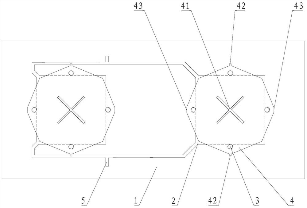
[0033] Please refer to Figure 1-4 , Embodiment 1 of the present invention is a base station antenna structure, which can be applied to a 5G base station.

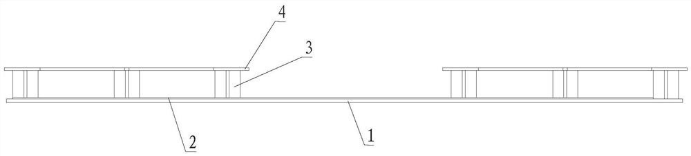
[0034] Such as figure 1 As shown, the substrate 1 and more than two antenna units are included, and this embodiment is described by taking two antenna units as an example. Each antenna unit includes a patch antenna 2, a support column 3 and a radiation sheet 4, combined figure 2 As shown, the patch antenna 2 and the support column 3 are arranged on the substrate 1, the radiation sheet 4 is arranged on the support column 3, and the projection of the radiation sheet 4 on the substrate 1 is consistent with the The above patch antennas 2 intersect; the patch antennas 2 of each antenna unit are connected.

[0035] In this embodiment, the patch antenna 2 can be disposed on the substrate 1 by printing. The radiation sheet 4 is a metal sheet or a copper-clad PCB board; the material of the support column 3 is a dielectric mate...


PUM


Abstract

The invention discloses a base station antenna structure and base station equipment. The base station antenna structure comprises a substrate and two or more antenna units, each antenna unit comprises a patch antenna, a support column and a radiation sheet, the patch antenna and the support column are arranged on the substrate, and the radiation sheet is arranged on the support column; the projection of the radiation sheet on the substrate intersects with the patch antenna; the patch antennas of the antenna units are connected; the radiation sheet is provided with a gap; the edge of the radiation sheet is provided with at least one branch knot and at least one cut corner. The radiation sheet is a metal sheet or a copper-clad PCB; and the supporting column is made of a dielectric material. According to the invention, high isolation performance between antenna systems can be realized, the production and assembly process can be simplified, and the cost can be reduced.

Description

technical field [0001] The present invention relates to the technical field of wireless communication, in particular to a base station antenna structure and base station equipment. Background technique [0002] In order to meet the high-speed communication requirements in the 5G era, it is necessary to use MIMO technology to increase the communication rate. The application of MIMO technology greatly increases the number of antenna elements and radio frequency channels of 5G base stations compared with traditional 2G-4G, and the space will become very narrow, which leads to a sharp deterioration in the isolation of 5G base stations. It is a key issue that must be considered, which also brings great challenges to base station antenna design. [0003] Compared with traditional base station antennas, the antenna isolation is mainly improved by separating strips and increasing the antenna spacing. In the case of a certain antenna size, the distance between the antennas cannot b...

Claims


Application Information

Patent Timeline
Patent Type & Authority Applications(China)
IPC IPC(8): H01Q1/52H01Q1/38H01Q1/36H01Q21/06H01Q1/24H04W88/08
CPCH01Q1/521H01Q21/065H01Q1/36H01Q1/38H01Q21/064H01Q1/246H04W88/08
Inventor 陈章福
Owner SHENZHEN SUNWAY COMM
Why Eureka
Try Eureka