Hydraulic holding cylinder for wing lift mechanism

a technology of hydraulic holding cylinder and wing lift, which is applied in the field of agricultural machinery, can solve the problems of dragging and dragging an excessive amount of load, and achieve the effect of reducing the overall width of the machine for transpor

Active Publication Date: 2006-07-11
MORRIS EQUIP LTD
View PDF7 Cites 48 Cited by
  • Summary
  • Abstract
  • Description
  • Claims
  • Application Information

AI Technical Summary

Benefits of technology

[0002]It is well known in the art to provide wing frame sections on farm machinery such as tillage and planting equipment wherein one or more wing frame sections can be folded up relative to a central main frame section to reduce the overall width of the machine for transport. In some five-section machines, for example, hydraulic cylinders fold outer wing sections almost 180° on top of inner wing frame sections and then other lift cylinders raise the inner wing frame sections into essentially upright positions to provide a compact piece of machinery for over-the-road travel or movement through gates and the like. It is also well known to provide lost motion couplings between the various lift cylinders and their wing frame sections so that, in the field-working position, the frame sections can be hinged relative to one another as need be to accommodate changes in ground contour encountered by the different sections of the machine. While this type of “flexing” action is important during field operations, it can also create problems during unfolding operations, particularly for the outer wing sections.
[0003]In this regard, the unfolding sequence of a five-section machine, for example, is that the inner wing frame sections are the first to unfold, followed then by the outer wing frame sections. As the inner wing frame sections are lowered down to their working positions and their tools come into ground engagement, their lift cylinders continue to extend an additional amount so as to position the lost motion coupling in an intermediate position, so that the inner wing sections can flex up and down to a certain extent relative to the main section. After the inner lift cylinders are thus fully extended, the outer lift cylinders unfold the outer wing frame sections and place them in the field working position as well. However, if the outer ends of the inner wing frame sections have dipped down slightly because their tools have sunk into soft ground or the ground is inclined, the tools on the outer wing frame sections near the hinge points may dig into the ground and bear an excessive amount of the load as the outer wing frame sections pivot down into their working positions. This is a particular problem where tools such as packer wheels project back from the rear of the outer wing frame sections and are supported by linkage that allows the packer wheels to drop down below the tra...

Problems solved by technology

While this type of “flexing” action is important during field operations, it can also create problems during unfolding operations, particularly for the outer wing sections.
However, if the outer ends of the inner wing frame sections have dipped down slightly because their tools have sunk into soft ground or the ground is inclined, the tools on the outer wing frame sections near the hinge points may dig into the ground and bear an excessive amou...

Method used


Image

  • Hydraulic holding cylinder for wing lift mechanism
  • Hydraulic holding cylinder for wing lift mechanism
  • Hydraulic holding cylinder for wing lift mechanism

Examples


Embodiment Construction

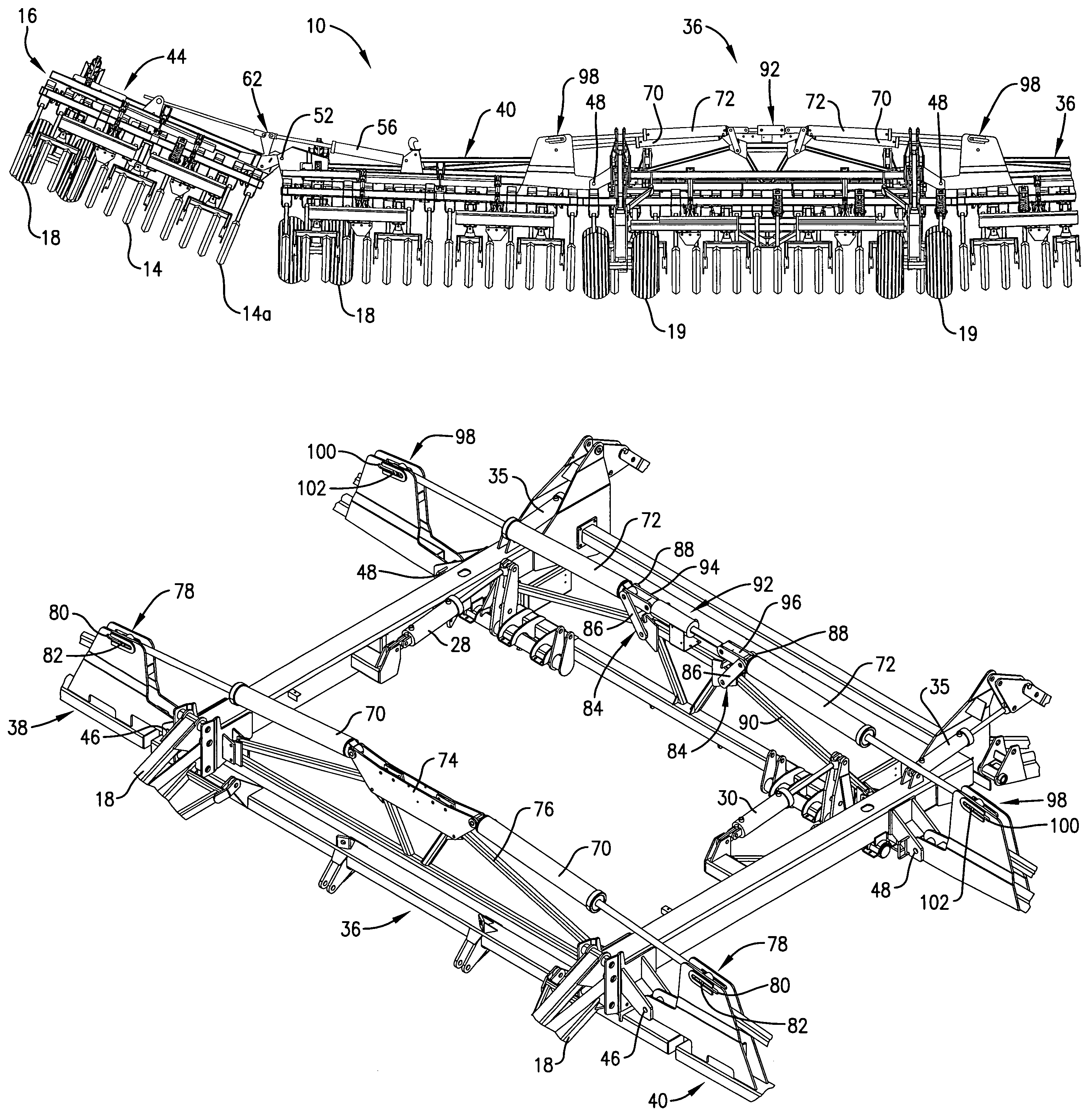
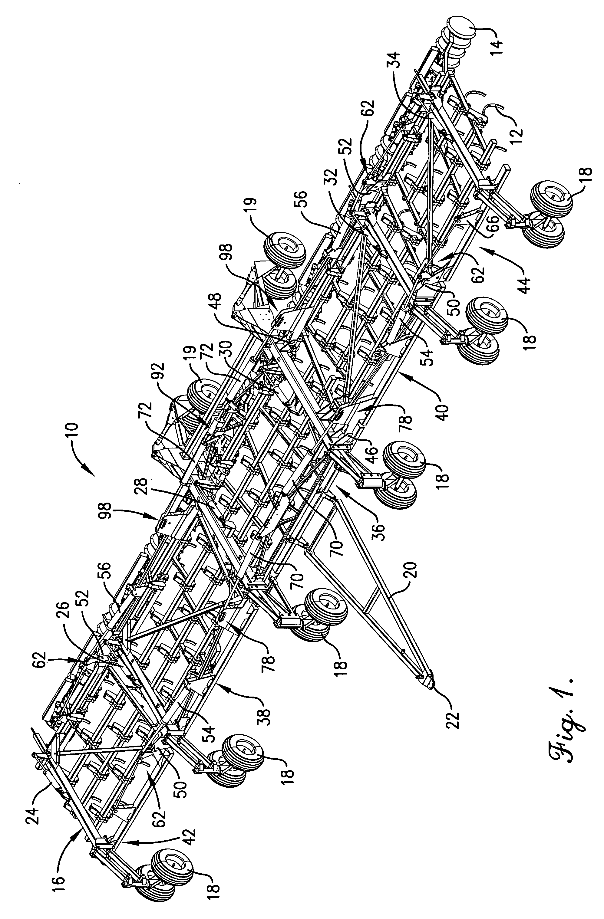
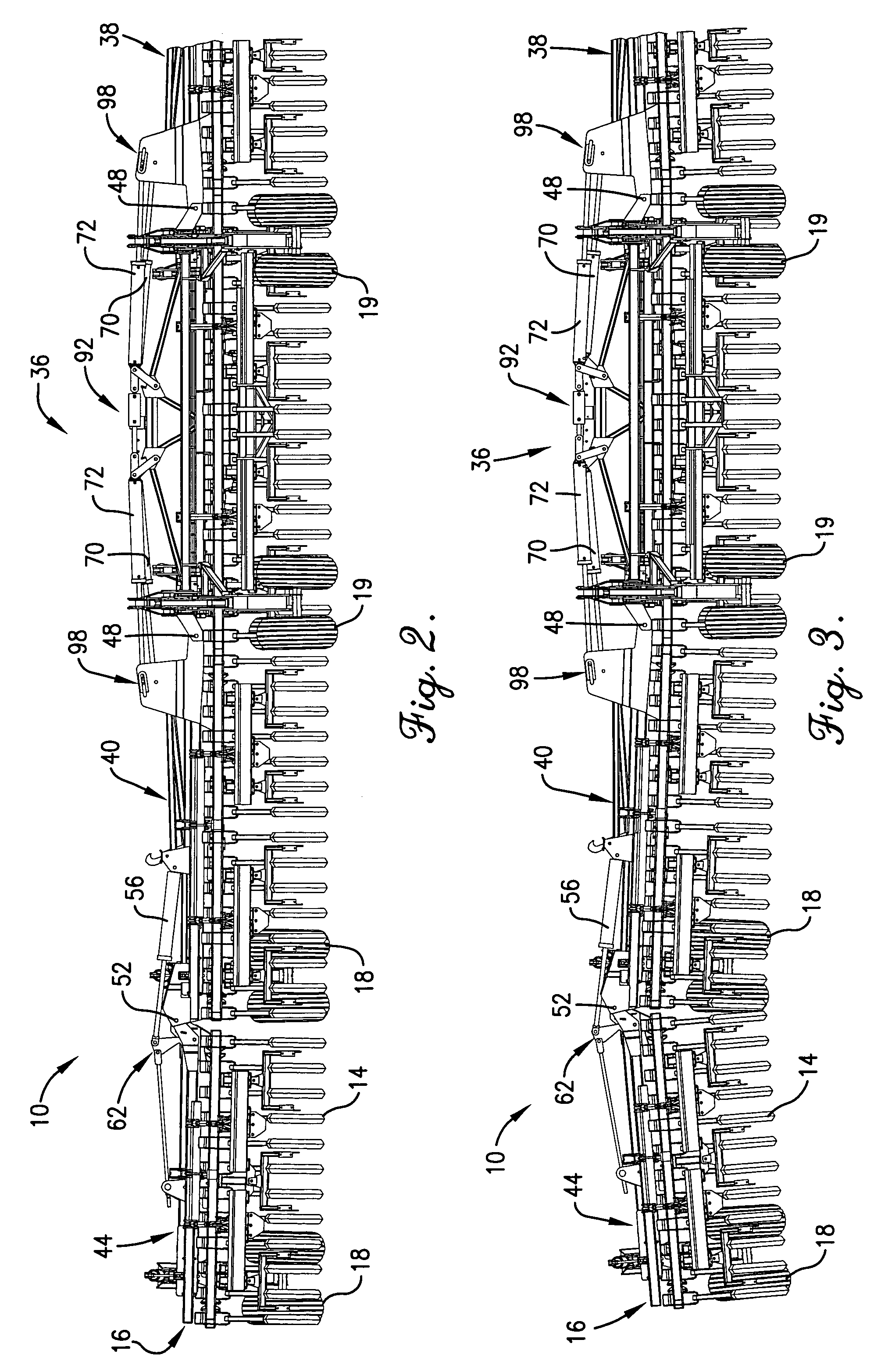
[0013]The present invention is susceptible of embodiment in many different forms. While the drawings illustrate and the specification describes certain preferred embodiments of the invention, it is to be understood that such disclosure is by way of example only. There is no intent to limit the principles of the present invention to the particular disclosed embodiments.

[0014]Machine 10 shown throughout the figures may take a variety of different forms. In the illustrated embodiment, the machine is provided with rows of openers 12 (with points removed) that are attached to the frame of the machine for making furrows in the soil as the machine passes over the ground. Gangs of packer wheels 14 are attached to the rear of the frame of the machine and are useful in closing furrows created by openers 12 after seeds or other substances have been deposited in such furrows utilizing delivery means not illustrated. The principles of the present invention are not limited to any particular type ...


PUM


Abstract

The transversely extending frame of a machine has a number of hingedly interconnected frame sections that may be raised and lowered by lift cylinders to convert the machine between a wide-spread working position and a folded-up transport position. Two lift cylinders for raising and lowering inner wing frame sections relative to the central main frame section are anchored at their inner ends to a hydraulically operated holding cylinder that effectively adjusts the positions of the anchor points of the lift cylinder in a lateral sense. Thus, when the holding cylinder is fully contracted, the inner wing frame sections may be lowered by their lift cylinders until the lift cylinders are fully extended, but the outer ends of the inner wing frame sections remain tilted upwardly to a certain extent. Thus, outer wing frame sections connected to the outer ends of the inner wing frame sections also remain slightly lifted off the ground until fully unfolded from the inner wing frame sections. Thereupon, the holding cylinder may be extended to gently lower all wing frame sections to the ground without damaging tools or mounting components for such tools.

Description

TECHNICAL FIELD[0001]The present invention relates to farm machinery and, more particularly, to machinery that utilizes a multiplicity of frame sections that are hingedly connected to one another for flexing in the field and for permitting fold up for transport, such as typically found in tillage equipment.BACKGROUND AND SUMMARY[0002]It is well known in the art to provide wing frame sections on farm machinery such as tillage and planting equipment wherein one or more wing frame sections can be folded up relative to a central main frame section to reduce the overall width of the machine for transport. In some five-section machines, for example, hydraulic cylinders fold outer wing sections almost 180° on top of inner wing frame sections and then other lift cylinders raise the inner wing frame sections into essentially upright positions to provide a compact piece of machinery for over-the-road travel or movement through gates and the like. It is also well known to provide lost motion c...

Claims


Application Information

Patent Timeline
IPC IPC(8): A01B49/00
CPCA01B73/046A01B63/32
Inventor DOBSON, DAVIDRYCZAK, DALE S.
Owner MORRIS EQUIP LTD
Why Eureka
Try Eureka