Traffic warning system

a technology of traffic warning and warning system, which is applied in the direction of electric signalling details, instruments, transportation and packaging, etc., can solve the problems of failure of the rail road detection system, and achieve the effect of enhancing the visibility of the sign to the motorist and enhancing the visibility of the sign

Inactive Publication Date: 2006-07-11
EVA SIGNAL CORP
View PDF16 Cites 157 Cited by
  • Summary
  • Abstract
  • Description
  • Claims
  • Application Information

AI Technical Summary

Benefits of technology

[0023]It will also be noted said present invention provides a novel system for actively alerting motorists, cyclists, or pedestrians to information provided by a sign such as a traffic sign or the like. One or more sensors are positioned near a road surface such as, for example, a roadway, a parking lot, or a parking garage. These sensors detect the presence of a vehicle on the road surface whereupon a controller may illuminate a plurality of light emitting devices arrayed on the surface of the sign to enhance the visibility of the sign to the motorist.
[0024]According to various aspects of the present invention, the system may be used to enhance visibility of signs along a roadway or at an intersection between two or more roadways, to regulate traffic through a construction zone, to provide traffic information to motorists traveling on a highway, or to provide vacancy information to motorists entering a parking lot or parking garage, for example.

Problems solved by technology

Thus, if the sensors or the implementation subsystem should notice an anomaly or are not working properly, the railroad detection system may be placed in a fail-safe condition.

Method used


Image

  • Traffic warning system
  • Traffic warning system
  • Traffic warning system

Examples


Embodiment Construction

[0059]Reference will now be made to a presently preferred embodiment of the present invention, examples of which are illustrated in the accompanying drawings.

Description of FIGS. 1–8

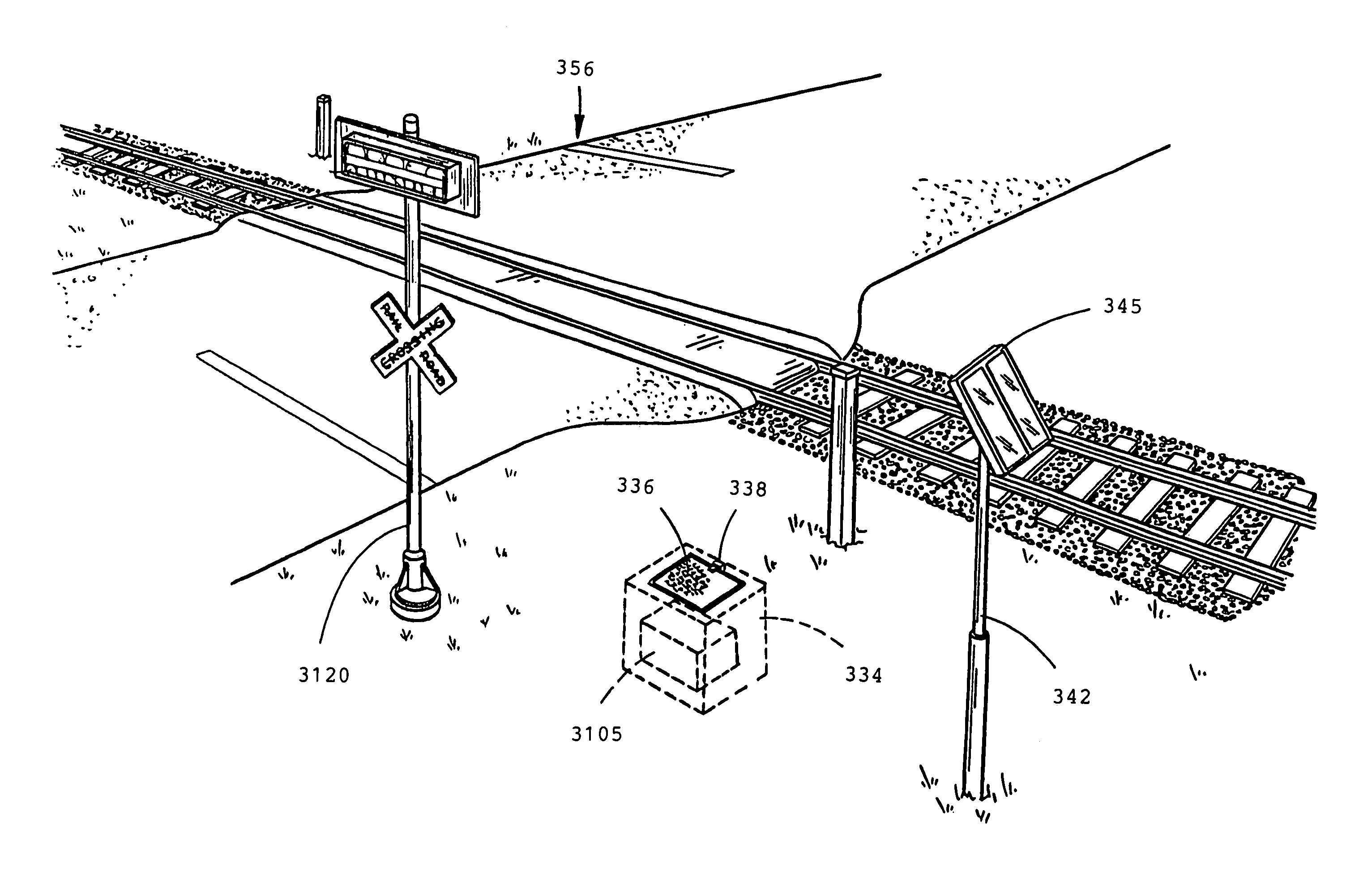
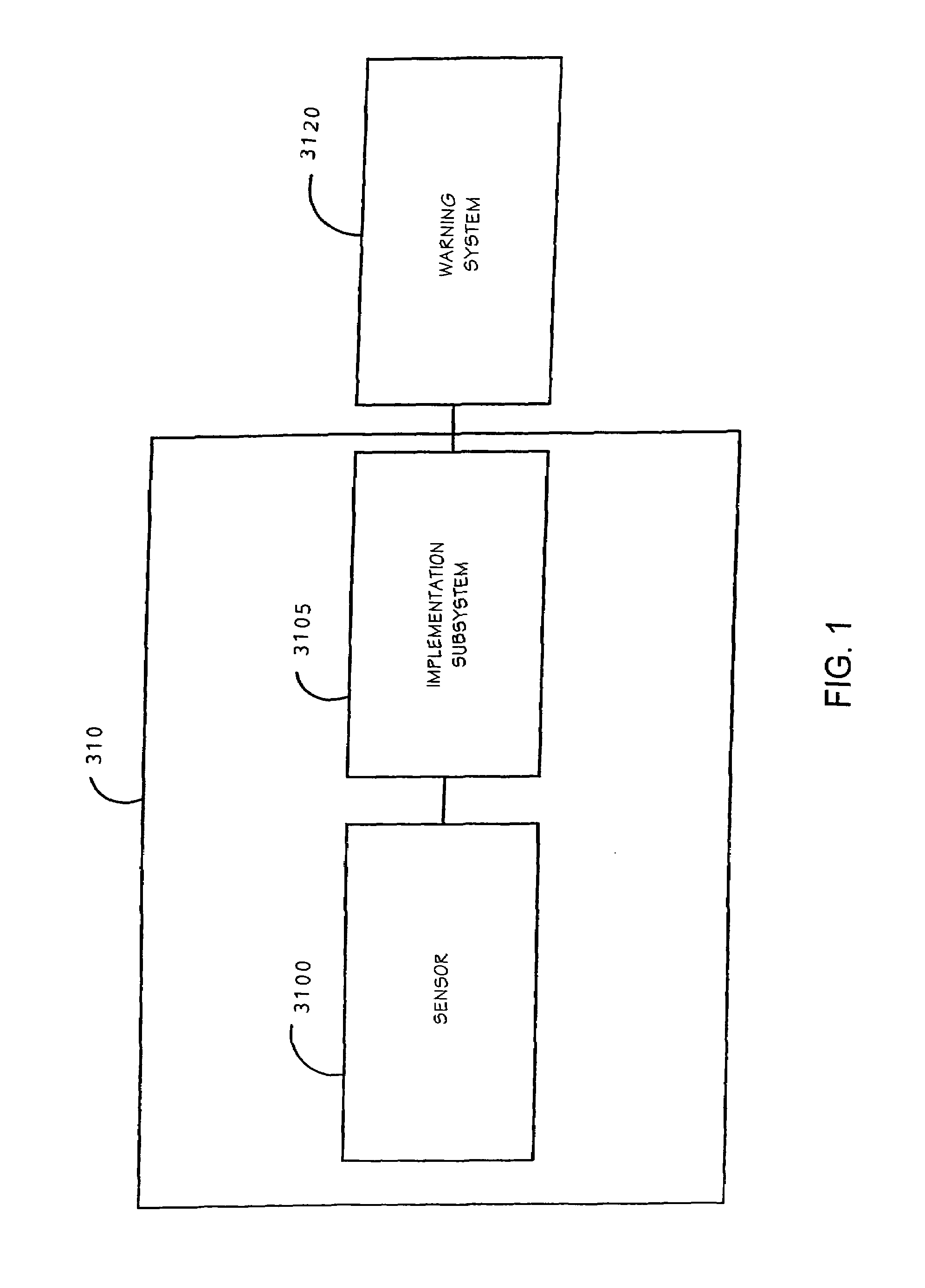
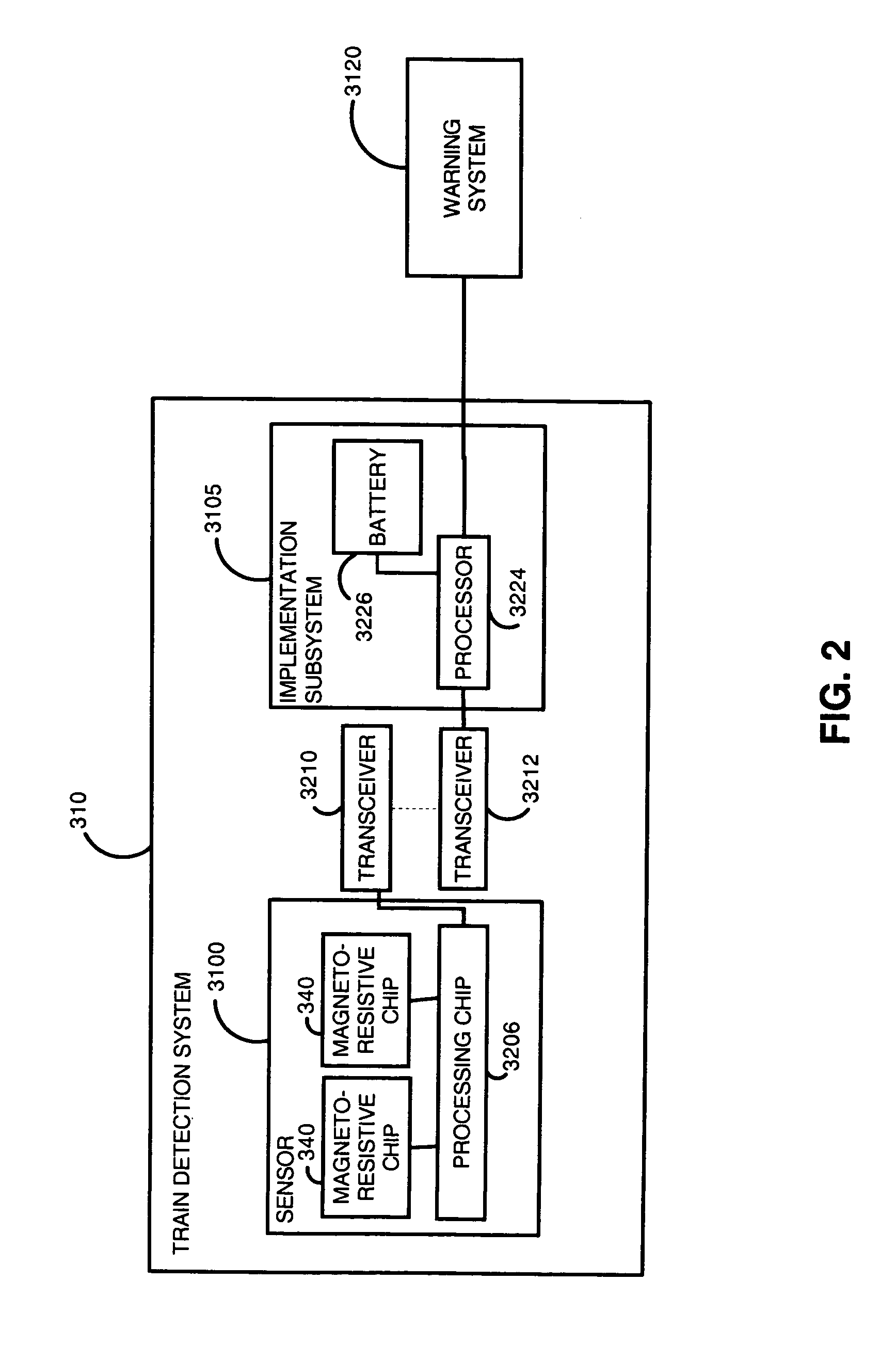
[0060]FIG. 1 depicts the universal and distinct subsystems of an exemplary train detection system 310 of the present invention. In an exemplary embodiment of the present invention, the train detection system 310 comprises a sensor 3100 and an implementation subsystem 3105. The train detection system 310 may be connected with a warning system 3120 in order to adequately alert motorists approaching a railroad crossing to the presence of an oncoming train. Since not all railroad crossings require complete detection and warning systems, the train detection system 310 of the present invention may also be installed with current installations in such a way that the sensor 3100 or the implementation subsystem 3105 may be installed independently to upgrade current installations. The train detection system 310 of ...


PUM


Abstract

The present invention is directed to a train detection system for detecting the velocity, presence, and direction of a railroad car which may be utilized in existing railroad crossing installations. The train detection system is suitable for self-testing of its components and if an anomaly has been detected, the train detection system is capable of placing the system in a fail-safe state. The train detection system of the present invention is also capable of constant communication between the sensor of said system and the implementing device of the train detection system via a wireless link.

Description

CROSS-REFERENCE TO RELATED APPLICATIONS[0001]The present application is a continuation-in-part of U.S. application Ser. No. 10 / 099,143 filed Mar. 15, 2002 now abandoned which is a continuation-in-part of U.S. application Ser. No. 10 / 027,920 filed Dec. 20, 2001 now abandoned which is a continuation-in-part of U.S. application Ser. No. 09 / 578,940 filed May 25, 2000 now abandoned, which is a continuation-in-part of U.S. application Ser. No. 09 / 448,953 filed Nov. 24, 1999 now abandoned, which is a continuation of U.S. application Ser. No. 09 / 344,477 filed Jun. 25, 1999 (now abandoned), which is a continuation-in-part of U.S. application Ser. No. 09 / 056,201 filed Apr. 6, 1998, now U.S. Pat. No. 5,954,299 issued Sep. 21, 1999; which is a divisional of U.S. application Ser. No. 08 / 710,147 filed Sep. 16, 1996, now U.S. Pat. No. 5,735,492, issued Apr. 7, 1998, which is a continuation-in-part of U.S. application Ser. No. 08 / 601,902 filed Feb. 15, 1996 now abandoned. Said application Ser. No. ...

Claims


Application Information

Patent Timeline
Patent Type & Authority Patents(United States)
IPC IPC(8): G08B1/08
CPCB61L23/06B61L29/28B61L29/30G08G1/164G08G1/042G08G1/096716G08G1/096758G08G1/096783
Inventor PACE, JOSEPH R.PACE, JOSEPH A.
Owner EVA SIGNAL CORP
Why Eureka
Try Eureka