
Software based single agent multipoint conference capability

Active Publication Date: 2006-07-11
WILMINGTON TRUST NAT ASSOC AS ADMINISTATIVE AGENT +1
View PDF25 Cites 38 Cited by
  • Summary
  • Abstract
  • Description
  • Claims
  • Application Information

AI Technical Summary

Problems solved by technology

While VoIP telephony works relatively well, its functionality has been limited to point-to-point applications.

Method used


Image

  • Software based single agent multipoint conference capability
  • Software based single agent multipoint conference capability
  • Software based single agent multipoint conference capability

Examples


Embodiment Construction

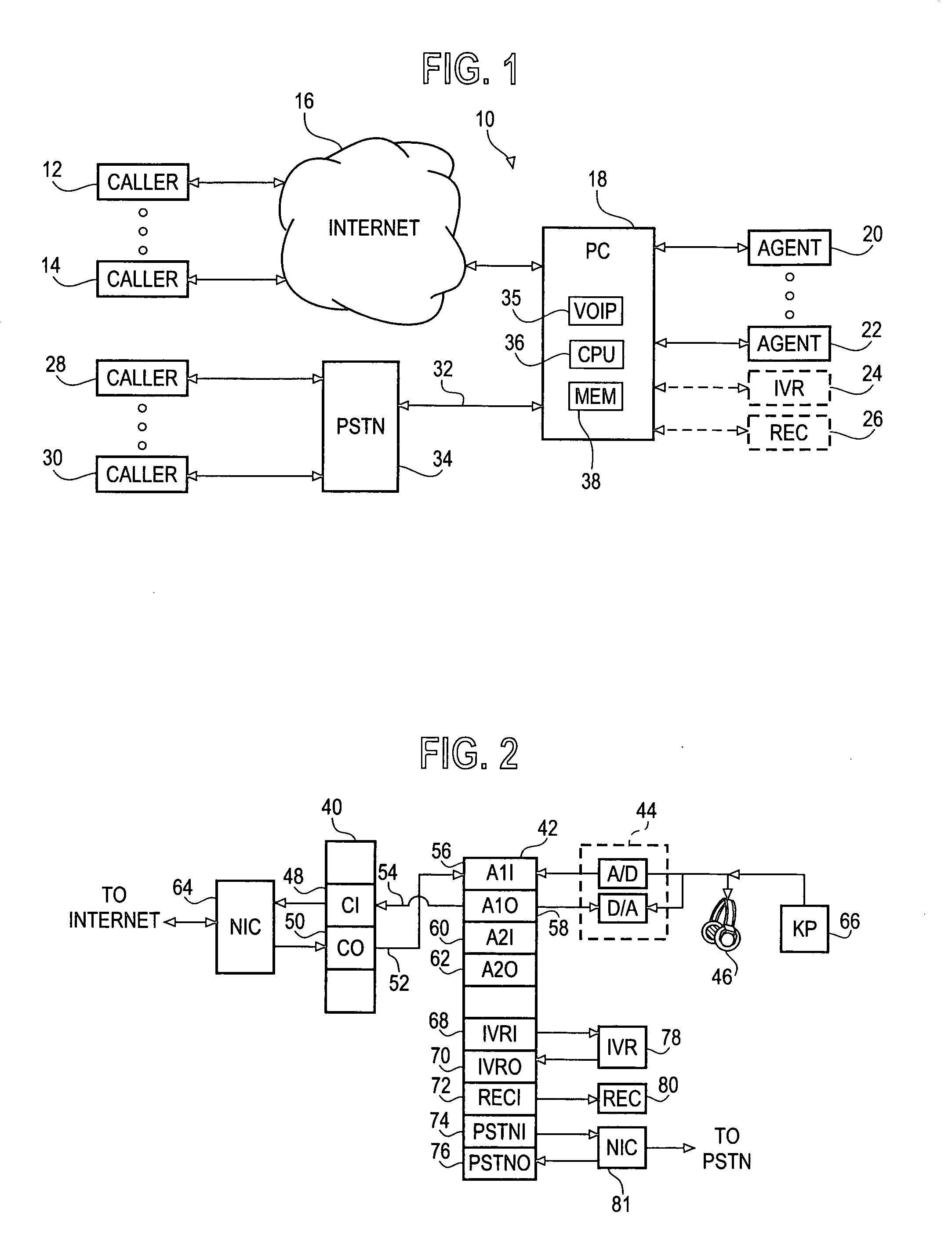
[0011]FIG. 1 is a block diagram of a VoIP conferencing system 10, shown generally under an illustrated embodiment of the invention and in a context of use. As shown, a PC 18 (offering a conferencing functionality) may be connected between callers 12, 14 (participants) connected through the Internet 16 and a number of other participants (e.g., agents 20, 22, interactive voice response (IVR) unit 24 or an audio recorder 26). Participants may also include callers 28, 30 connected to a VoIP conference call at least partially through switched circuit connections established through the public switched telephone network 34.

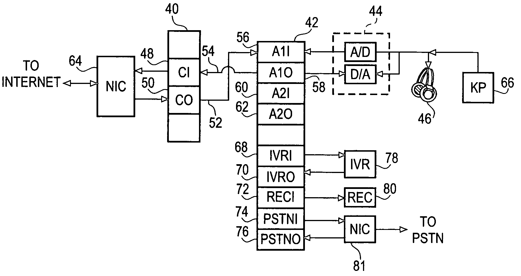
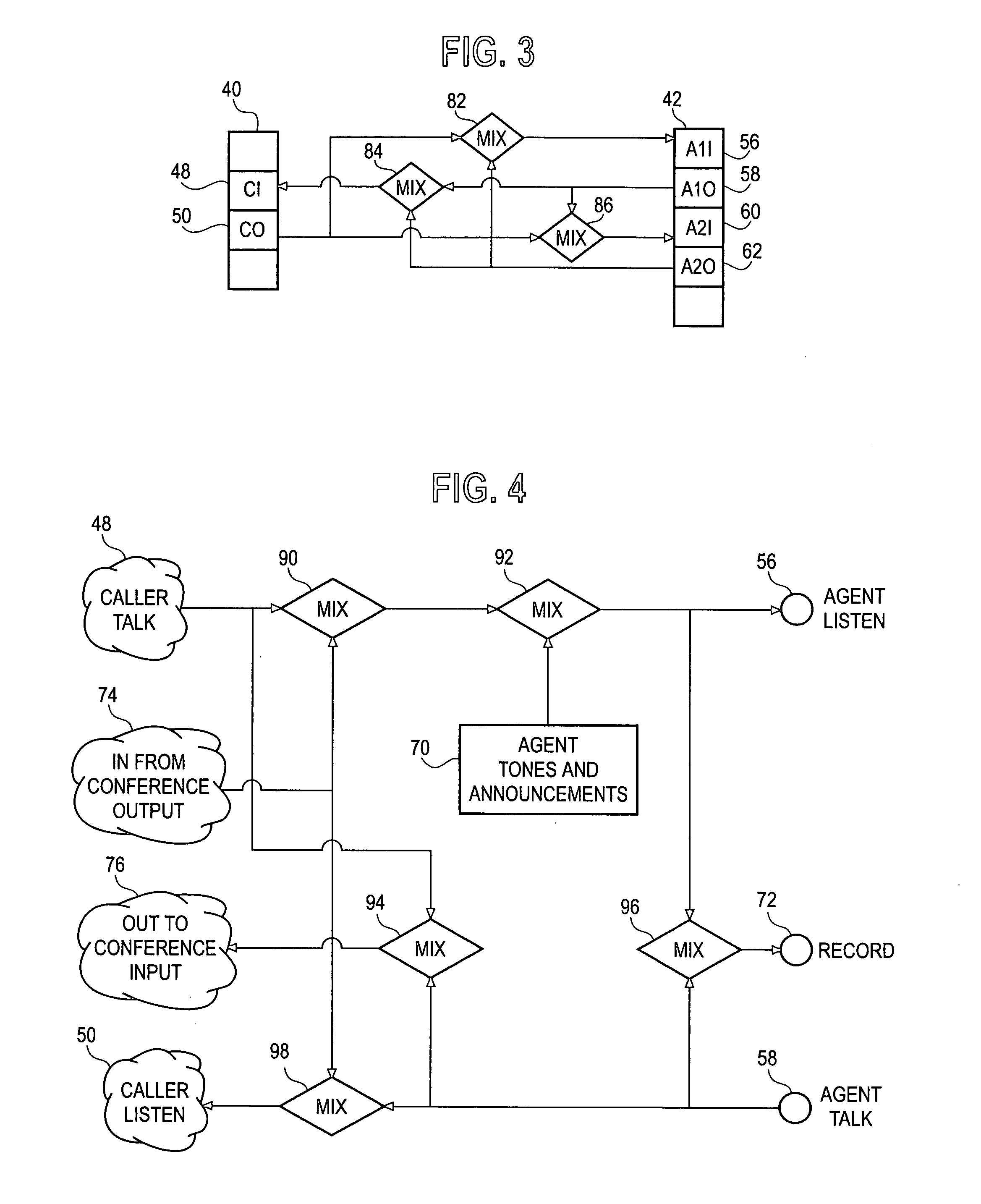
[0012]FIG. 2 depicts structure within the PC 18 which may be used to process VoIP information between a caller 12, 14 and an agent 20, 22. For purposes of explanation, an Internet protocol stack (PS) 40 and enterprise PS 42 may be understood to delineate the boundaries of those VoIP processes which occur within the CPU 36 and those processes which occur outside the CPU ...


PUM


Abstract

A method and apparatus are provided for providing a three-party connection among a first, second and third call participant during a voice-over-Internet-Protocol (VoIP) telephone call. The method includes the steps of providing a respective first and second port within a transceiving terminal for receiving VoIP voice information of the VoIP telephone call from the first and second call participants, mixing the VoIP information from the ports of the first and second call participants and transferring the mixed VoIP information to the third call participant.

Description

FIELD OF THE INVENTION[0001]The field of the invention relates to telephony and more particularly to VoIP telephony.BACKGROUND OF THE INVENTION[0002]Voice over Internet Protocol (VoIP) telephony is a rapidly growing alternative to switched circuit telephony. Typically, a user purchases a VoIP software package and installs it on his personal computer (PC). To initiate a voice exchange with another party, the user enters an IP address of the other party and, if the other party has a similar software package, an exchange of voice information occurs.[0003]Audio information is sampled by the VoIP package once every 10–30 ms. The samples are encoded into an IP packet containing an IP address of the other party. The packet is transferred over a connection to the Internet, and, ultimately, to a PC of the other party.[0004]Within the PC of the other party, the sample is recovered and converted back into an analog signal. The analog signal is applied to a set of earphones or speaker and the o...

Claims


Application Information

Patent Timeline
IPC IPC(8): H04L12/16H04L12/18H04M3/56H04M7/00
CPCH04L12/1822H04M7/006H04M3/56H04M2203/5018
Inventor PETERS, MICHAEL
Owner WILMINGTON TRUST NAT ASSOC AS ADMINISTATIVE AGENT
Learn More