
Output current and voltage regulating interface for remote terminal

Active Publication Date: 2006-07-11
ADTRAN
View PDF1 Cites 2 Cited by
  • Summary
  • Abstract
  • Description
  • Claims
  • Application Information

AI Technical Summary

Benefits of technology

[0011]For increasingly larger values of load impedance and corresponding increased values of load voltage, the magnitude of the by-pass current will eventually become equal to the maximum value of IREF. Once the load impedance reaches a value where the magnitude of the bypass current is equal to the

Problems solved by technology

In comparison to a traditional central office installation, ambient conditions (such as temperature) within a remote terminal can be relatively austere or extreme, and may negatively impact the performance of equipments that had historically performed satisfactorily in a traditional central office.

Method used


Image

  • Output current and voltage regulating interface for remote terminal
  • Output current and voltage regulating interface for remote terminal
  • Output current and voltage regulating interface for remote terminal

Examples


Embodiment Construction

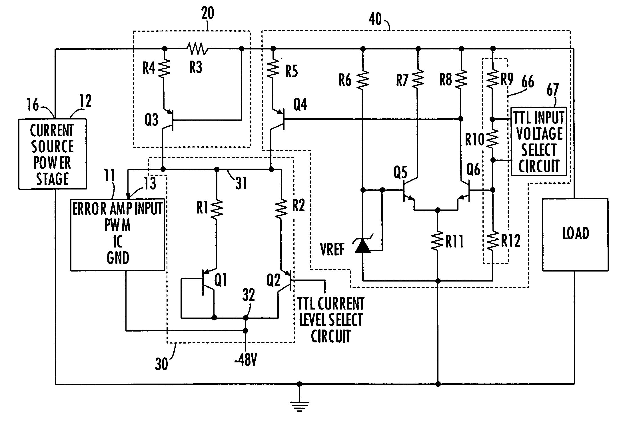
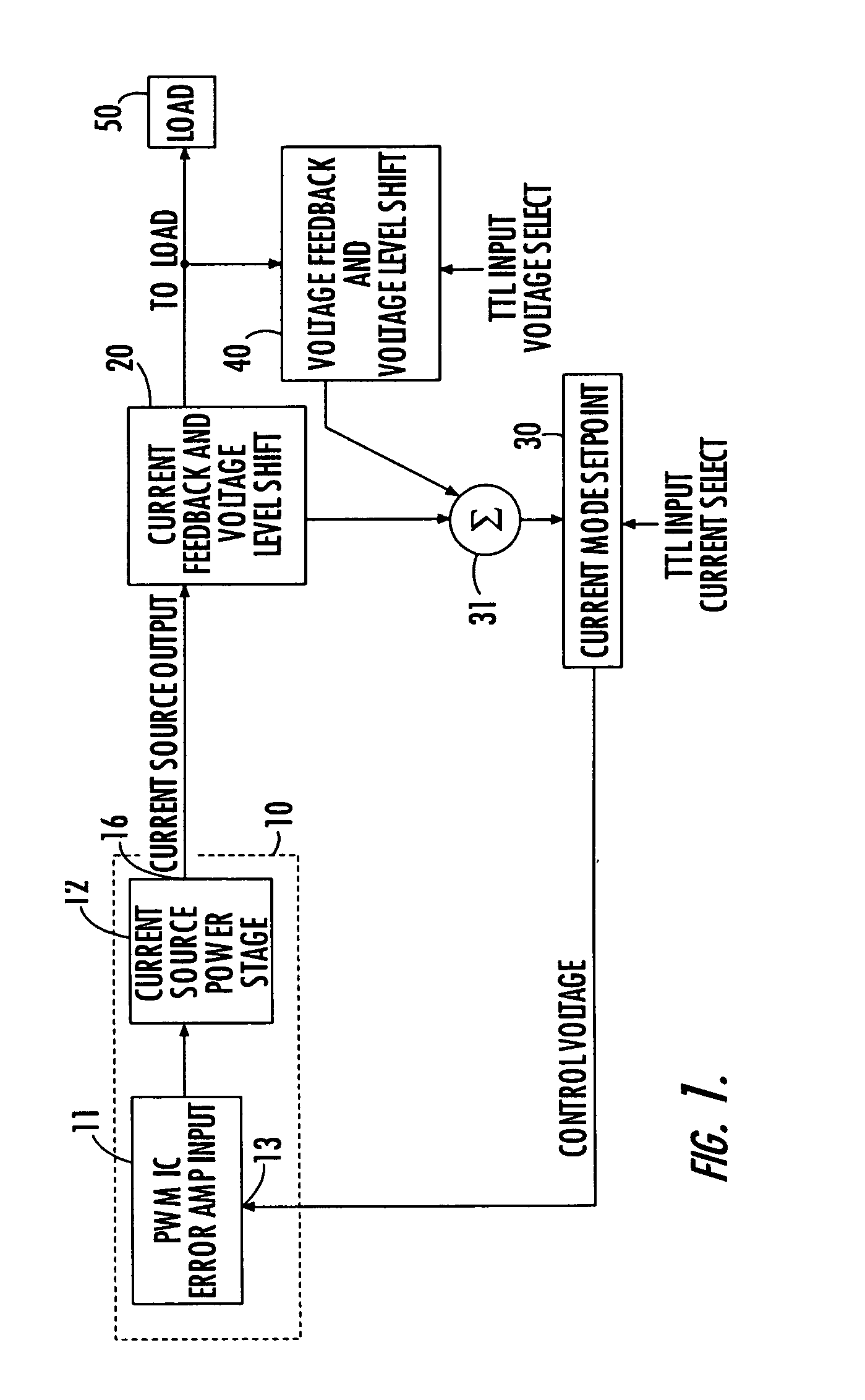
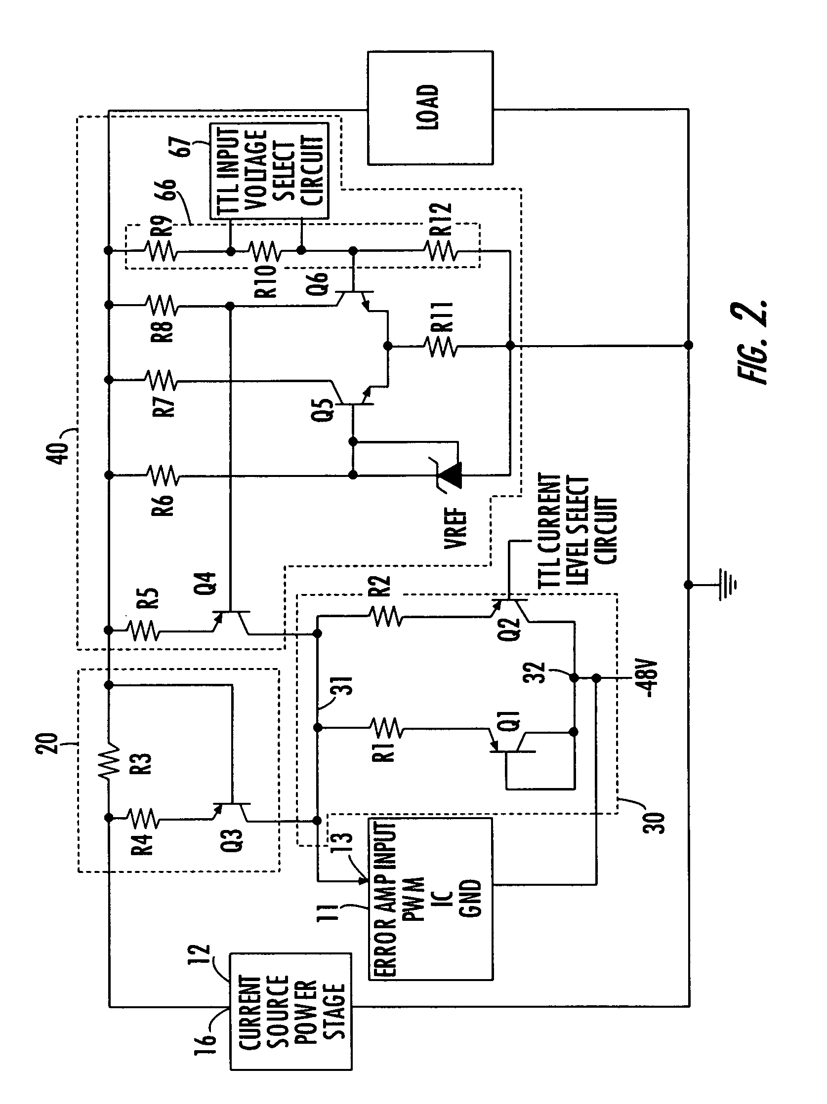
[0017]Before detailing the regulated power supply interface of the present invention, it should be observed that the invention resides primarily in a new and improved circuit architecture that is configured to be interfaced with standard regulated power supply components, such as those of a pulse width modulated supply of the type used in telecommunication equipment powering applications. Consequently, such conventional power supply components have, for the most part, been depicted in readily understandable block diagram form in order to show only those specifics that are pertinent to the present invention, and not obscure the disclosure with details which will be readily apparent to those skilled in the art having the benefit of the description herein.

[0018]Attention is now directed to FIG. 1, which is a reduced complexity diagram of the overall architecture of the regulated power supply interface of the present invention, and the manner in which it interfaces a controllable power ...


PUM


Abstract

A regulated power supply interface has a current feedback and voltage level shift circuit that monitors power supply output (load) current and controllably diverts current to a current reference node. A differential amplifier-based, voltage feedback and voltage level shift circuit monitors the load voltage and controllably diverts output current to the current reference node. A current mode setpoint circuit has multiple voltage dropping current paths, through one or more of which a summation of the diverted load currents are programmably directed, to generate a control voltage for controlling the operation of a pulse width modulator unit of the regulated power supply.

Description

FIELD OF THE INVENTION[0001]The present invention relates in general to power supply systems and subsystems therefor, and is particularly directed to a regulated power supply interface that provides current and voltage regulation in the presence of changing conditions of load and installation ambient temperature, making the regulation interface particularly useful in a remote telecommunications terminal supplying power to a device such as, but not limited to a coin-operated telephone, in which load (impedance) parameters vary during the course of changes in operational conditions of the device.BACKGROUND OF THE INVENTION[0002]The ability of regulated power supplies and interfaces therefor to maintain their intended performance over changing operational and environmental conditions is a critical aspect to the successful deployment and operation of a variety of electronic systems and components thereof. Within the telecommunication industry, for example, the load and powering requirem...

Claims


Application Information

Patent Timeline
IPC IPC(8): H04M1/00H04M19/00
CPCH04M19/00
Inventor BAHL, ERIK STEFANMCGARY, JOHN S.SMITH, SCOTT L.
Owner ADTRAN
Learn More