Electromagnetic Coupler

Inactive Publication Date: 2021-04-15
ROBINSON JR KAY C
View PDF0 Cites 0 Cited by
  • Summary
  • Abstract
  • Description
  • Claims
  • Application Information

AI Technical Summary

Benefits of technology

[0002]Using the same principal of how the relay operates, an electromagnet to induce and transfer energy, and replacing the mechanical switch with a transistor the operating potential of the relay as well as potential uses increases sig

Problems solved by technology

This causes a contact bounce or debouncing effect.
Because of the mechanical

Method used


Image

  • Electromagnetic Coupler
  • Electromagnetic Coupler
  • Electromagnetic Coupler

Examples


Example

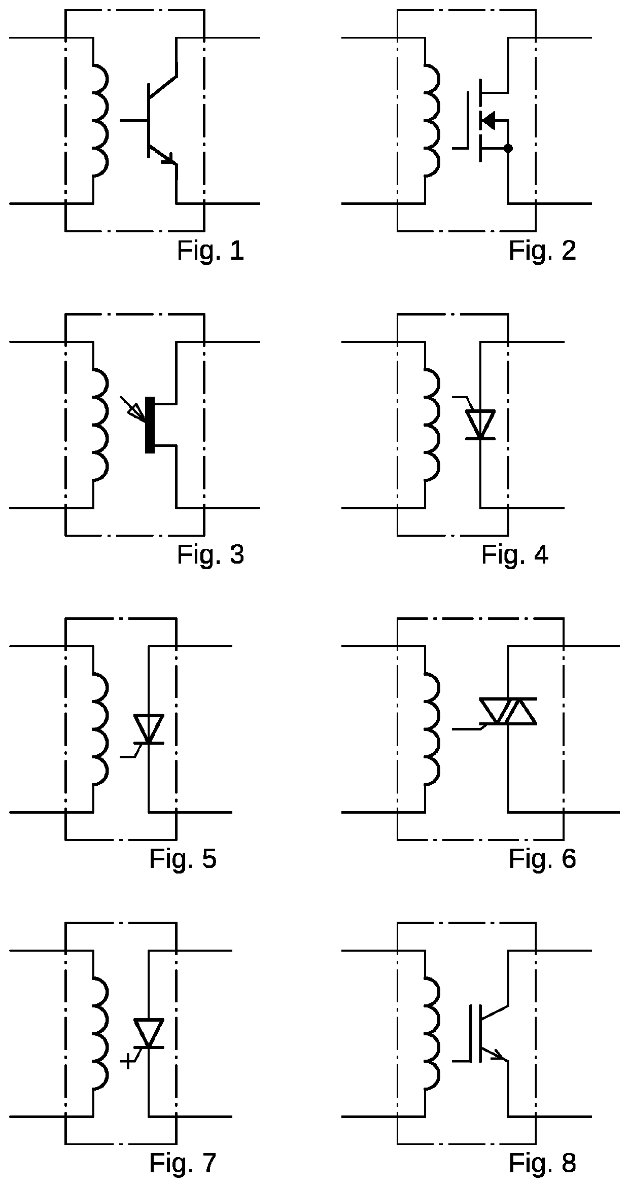
[0019]FIG. 1 uses a coil in the same casing as a BJT transistor. When an electrical current passes through the coil and is energized, an electromagnetic field will develop and induce a voltage onto the base of the transistor. Depending on the q-point of the internal BJT transistor the induced voltage as well as current will be amplified, or the transistor will act as a switch moving between its saturation and cutoff modes. This will be accomplished without any electrical / electronic connection between the coil and the BJT transistor.

[0020]FIG. 2 uses a coil in the same casing as a FET transistor. When an electrical current passes through the coil and is energized, an electromagnetic field will develop and induce a voltage onto the gate of the transistor. Depending on the q-point of the internal FET transistor the induced voltage as well as current will be amplified, or the transistor will act as a switch moving between its saturation and cutoff modes. This will be accomplished withou...


PUM


Abstract

The electromagnetic coupler uses a coil to induce voltage onto a transistor. By controlling the amount of current that flows through the coil, one is able to can control the strength of the magnetic field emitted by the inductor. And by the controlling the q-point of the transistor, the amount voltage and current induced onto the transistor it can then potentially be used as a switch or an amplifier without any electrical/electronic connection to the internal coil. The use of a transistor enables high speed switching and the potential amplification of communication signals.

Description

BACKGROUND OF THE INVENTION[0001]The original purpose of invention was to create a relay with the ability operate at high speeds. Relays use electromagnetism to mechanically operate a switch. This causes a contact bounce or debouncing effect. Because of the mechanical switch, the speeds or frequencies at which the relay can operate are limited. By replacing the mechanical switch with an electronic one the operating potential of the relay increases.SUMMARY OF THE INVENTION[0002]Using the same principal of how the relay operates, an electromagnet to induce and transfer energy, and replacing the mechanical switch with a transistor the operating potential of the relay as well as potential uses increases significantly. Also depending on how the transistor is biased it can even be used as an amplifier. Electric power and electronic communication can be transferred from the coil to the transistor without any electrical / electronic connection.BRIEF DESCRIPTION OF THE DRAWINGS[0003]FIG. 1 is ...

Claims


Application Information

Patent Timeline
IPC IPC(8): H01H47/32H01H47/36H03K17/56H03K17/0814
CPCH01H47/325H03K17/0814H03K17/56H01H47/36H03K17/605H03K17/61H03K17/689H03K17/691
Inventor ROBINSON, JR., KAY C
Owner ROBINSON JR KAY C
Why Eureka
Try Eureka