Multiple-power engine device

Inactive Publication Date: 2006-06-22
TSENG CHUN LIN
View PDF16 Cites 2 Cited by
  • Summary
  • Abstract
  • Description
  • Claims
  • Application Information

AI Technical Summary

Benefits of technology

[0048] A rotation flywheel cylinder of the present invention comprises eight sets of gear-drive eccentric top-raised cylinder drives which are able to operate twice the vehicle output power processes of intake, compression, power and exhaust in a rotation cycle, so as to increase the operating speed of the cylinder drives themselves with only a short distance movement, further to raise accelerating rotation force and then relatively to reduce the fuel consumption hugely.
[0049] Accordingly, traditional cranks and cranksh

Problems solved by technology

However, on the contrary, to focus on present car engine development, the car still stays in the stage of reciprocating piston structures and is not able to release from the bottleneck of this original designed structure.
While the engine are accelerated the second time, the power energy is wasted here for the continuing increase of the dead angle time.
However, the design exists defects, comprising: (1) Gap time problem, reducing instantaneous thrust efficiency during the four-stroke processes; (2) Long operating time problem, influencing power efficiency because of a complete power shaft output (360 degree) requiring twice cycles (720 degree) of the four-stroke processes of intake, compression, power, exhaust in the cylinder; (3) Much cooling water to cool down the engine because of heat generated from the piston reciprocation at fixed spot easily damaging the cylinder; (4) Too many parts increasing the cost of maintenance and repair, including one sparkling plug, two valve sets, and a camshaft, in such a complex mechanism; (5) Up to 70% power loss from the mechanical operation and heat vaporization, and feedback of the engine power output because of the large-sized, heavy-weighted engine and the crank operating 720 degree to complete power output only once; (6) Fuel consumption raising sharply while the engine rotation speed and torque being increased because of its original design limitation; and (7) Heavy

Method used


Image

  • Multiple-power engine device
  • Multiple-power engine device
  • Multiple-power engine device

Examples


Example

[0065] The following descriptions are of exemplary embodiments only, and are not intended to limit the scope, applicability or configuration of the invention in any way. Rather, the following description provides a convenient illustration for implementing exemplary embodiments of the invention. Various changes to the described embodiments may be made in the function and arrangement of the elements described without departing from the scope of the invention as set forth in the appended claims.

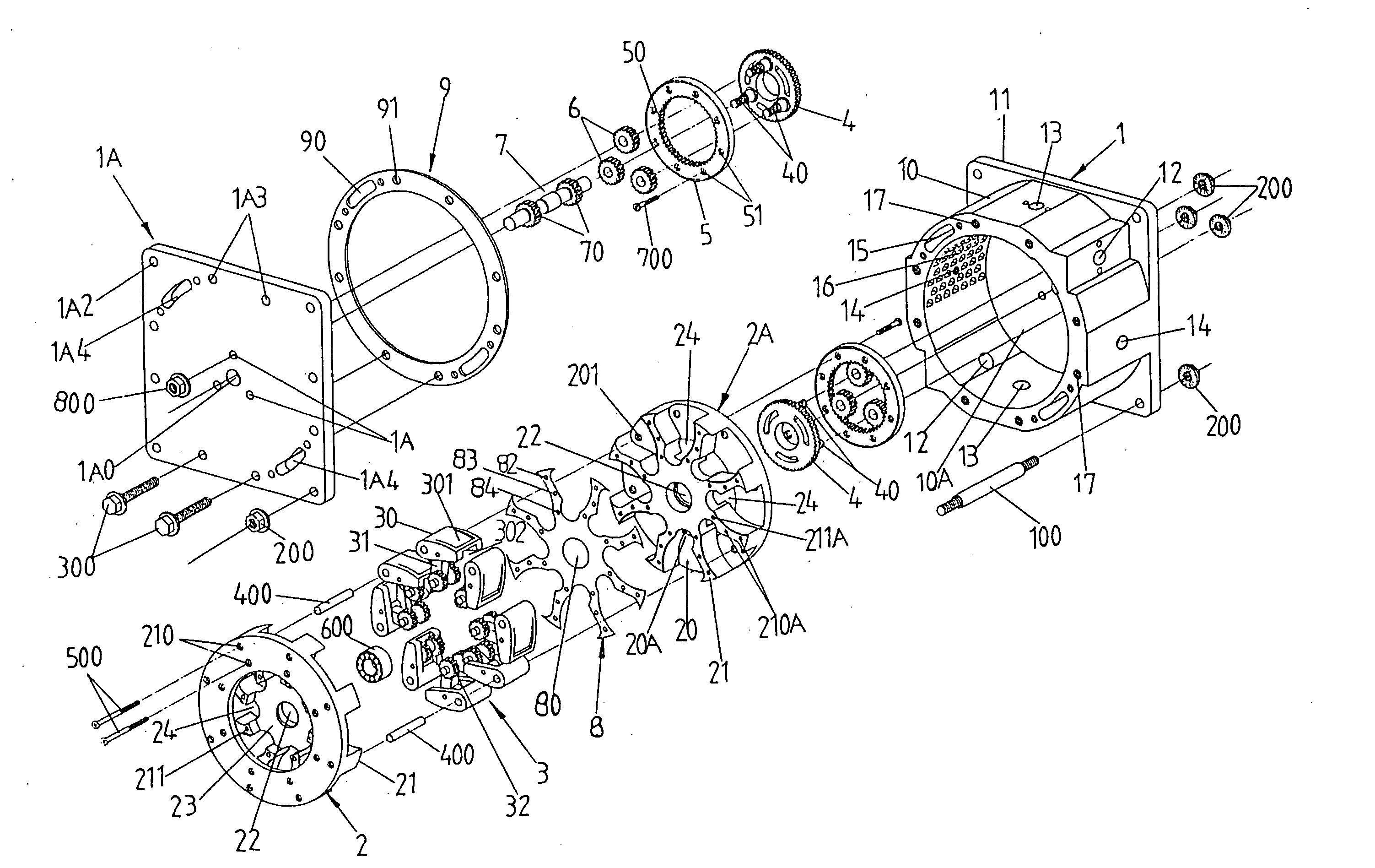
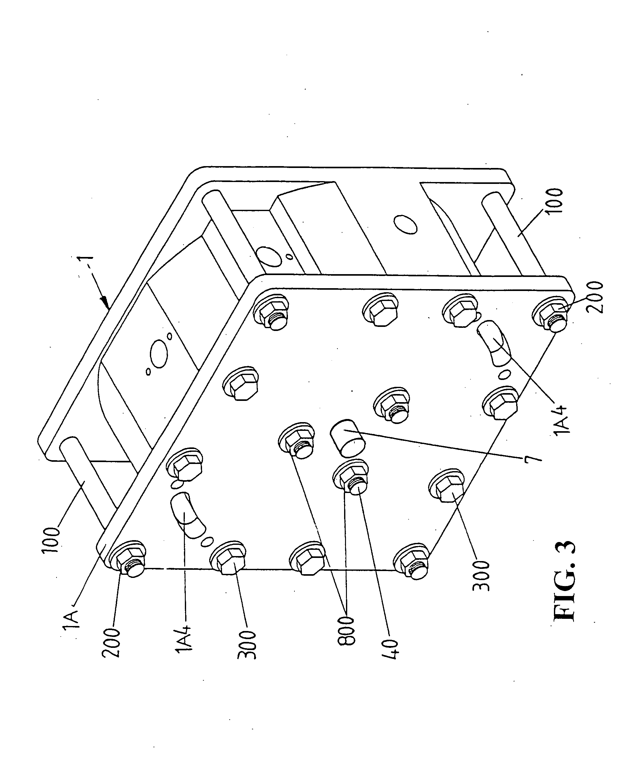
[0066]FIGS. 3-6 are three-dimensional, three-dimensional exploded, exploded plane and assembled cross sectional plane views of an engine in the present invention.

[0067] The main structure of the engine comprises: [0068] (1) An engine case 1 having around case 10 and a square base 11 formed in an inverted T-shape, the round case 10 having outer surfaces fabricated to a wave-like indented shape and an engine chamber 10A inside, the outer surfaces having two diametrically symmetrical intake holes...


PUM


Abstract

The present invention relates to a multiple-power engine device, and more particularly, to a cylinder mechanism comprising multi-sets of gear-drive eccentric top-raised cylinder drives inside an engine case being able to operate twice the processes of intake, compression, power and exhaust in a cycle to gain multiple of power output. The primary parts comprise one engine case, two cylinder bases, one multi-sets of gear-drive eccentric top-raised cylinder drives, two inner-teeth idle gearwheels, one fixed external gearwheel, one driving gear shaft, two eight-claw shape and annular shape anti-leak cylinder gaskets, one bearing and three small gears intermeshed with inner teeth of the inner-teeth idle gearwheel. According to assembly of above-described parts, a generator is able to start and drive the driving gear shaft, coupled with the three small gears inside a inner-teeth idle gearwheels to drive rotating the inner-teeth idle gearwheels and the two cylinder bases locked together with the inner-teeth idle gearwheels, where the two small gears in one of the multi-set of gear-drive eccentric top-raised cylinder drives intermesh with and encircle the two fixed external gears. Thus, the engine is driven and then operates under the explosion output processes of intake, compression, power and exhaust, which raises top the multi-sets of gear-drive eccentric top-raised cylinder drives by compression and explosion and bends multi-set driving arms by gearing eccentrically, so as to generate re-acceleration driving power by itself. The continuous rotation engine is able to drive rotating the multi-sets of gear-drive eccentric top-raised cylinder drives and gain double kinetic energy in a 360 degree cycle from operating twice the processes of intake, compression, power and exhaust for increasing the operating speed of the cylinder drives themselves with only a short distance movement and enhancing power output instantly, so as to increase the vehicle engine speed continuously and then relatively to reduce the basic fuel consumption less than half of a traditional vehicle does.

Description

BACKGROUND OF THE INVENTION [0001] (a) Technical Field of the Invention [0002] The present invention relates to a multiple-power engine device and the primary parts comprise: [0003] (1) An engine case formed in an inverted T-shape having two sets of diametrically symmetrical intake holes, exhaust holes and sparkling plug screw holes on outer surfaces of a round case of the engine case, the outer surfaces fabricated to a wave-like indented shape, two diametrically symmetrical cooling water holes and several screw holes on open end surface of the round case, and two sets of diametrically symmetrical air-pressurized thrust mesh holes in the same pitch on inner surface of the round case; [0004] (2) Two cylinder bases formed and shaped like two flywheel bases having eight sets of containing crooked concaved cells formed an eight-claw convex surface on one side of each cylinder base, the eight-claw surface facing to the another one, pin holes formed at the bottom of each containing crooke...

Claims


Application Information

Patent Timeline
IPC IPC(8): F02B53/00F01B13/04F04C18/00F04C2/00
CPCF01C1/44F01C11/002F01C17/02
Inventor TSENG, CHUN-LIN
Owner TSENG CHUN LIN
Why Eureka
Try Eureka