
Apparatus for producing electrolyzed water

Active Publication Date: 2018-05-17
LEE JAE YONG +1
View PDF6 Cites 2 Cited by
  • Summary
  • Abstract
  • Description
  • Claims
  • Application Information

AI Technical Summary

Benefits of technology

The present invention is an apparatus for generating electrolyzed water that has a high production efficiency of hydrogen water and can generate a high-concentration hydrogen water. The apparatus can suppress the temperature increase during operation, prevent the reduction of the dissolved-hydrogen amount due to the gasification of the hydrogen and the breakage of the ion-exchange membrane due to heat, increase the stability during operation and stably generate a high-concentration hydrogen water.

Problems solved by technology

However, the apparatus described in Patent Document 1 is an apparatus for electrolyzing pure water with an electrolyte added thereto, and finds difficulty in generating hydrogen water by electrolyzing the water filtered with, for example, a reverse osmosis membrane.
However, these apparatus mainly aims at obtaining an electrolyzed water comprising hypochlorous acid or an electrolyzed water comprising ozone using a porous anode, but does not aim at obtaining hydrogen water having a high concentration.
However, when the areas of the electrodes are reduced in order to incorporate the apparatus within a limited space, there occurs a problem that no highly-concentrated hydrogen water can be obtained.
Moreover, when electrodes and an ion-exchange membrane are incorporated in a small space, the temperature of water or the like flowing in the electrodes, the ion-exchange membrane and the apparatus increases during operation of the apparatus, and hence there occurs a problem of reduction of the dissolved-hydrogen amount due to the gasification of hydrogen or the breakage of the ion-exchange membrane.
The conventional apparatuses for generating electrolyzed water, including the above-described apparatuses are all far from solving these problems.

Method used


Image

  • Apparatus for producing electrolyzed water
  • Apparatus for producing electrolyzed water
  • Apparatus for producing electrolyzed water

Examples


example 1

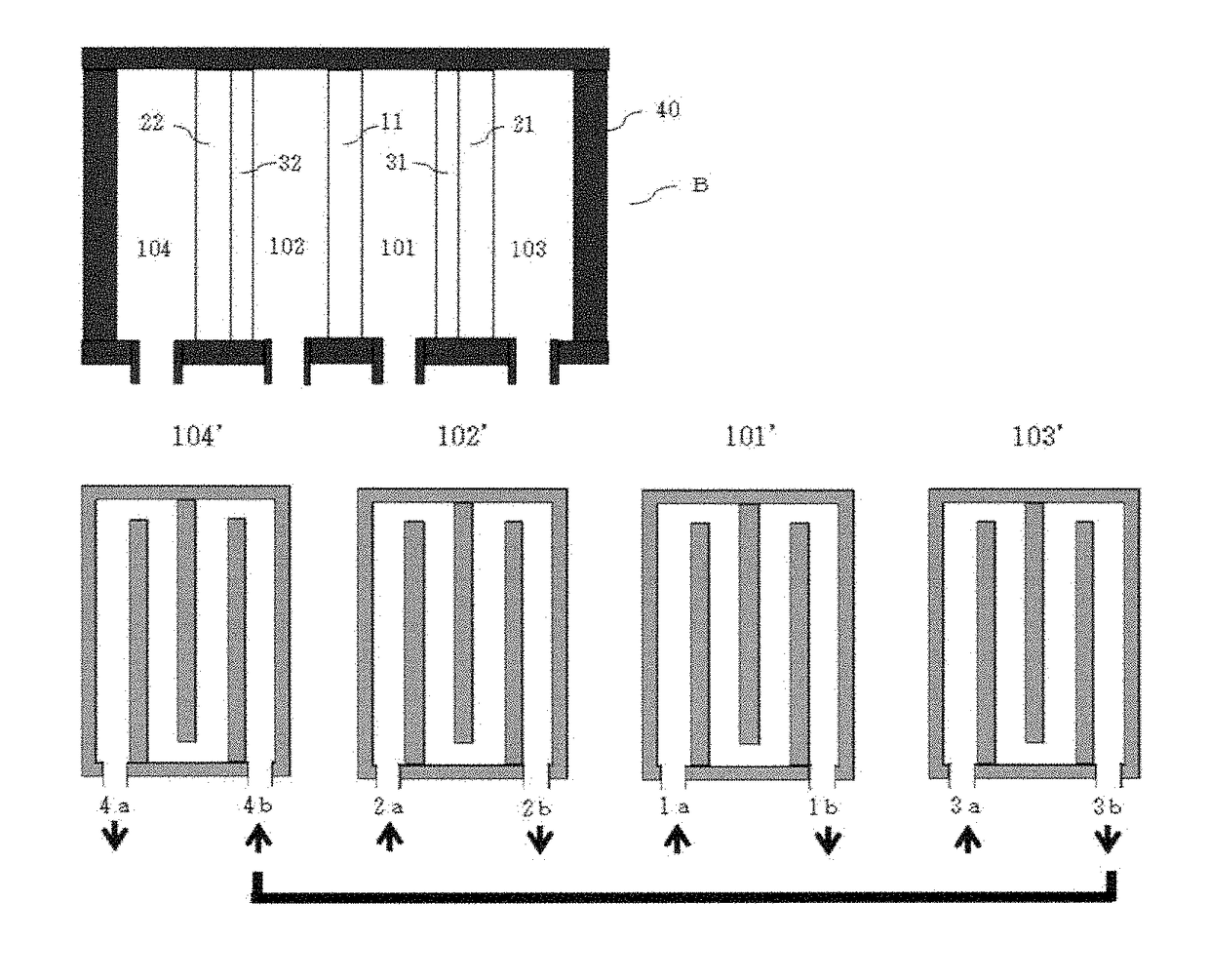
[0039]Electrolyzed water was produced by using the apparatus for generating electrolyzed water shown in FIG. 2. The water treated with a reverse osmosis membrane (total dissolved solid content (TDS): 1 mg / 1, water temperature: 20° C.) was fed to the feed openings 1a, 2a and 3a, at a rate of 50 cc / min for 1a and 2a, and at a rate of 1000 cc / min for 3a. The dissolved hydrogen concentration (DH), the oxidation-reduction potential (ORP) and the pH of the electrolyzed water discharged from the discharge opening 4a were measured. The results thus obtained are shown in Table 1. The electric current value (1) is the value measured between the anode plate and the first cathode plate, and the electric current value (2) is the value measured between the anode plate and the second cathode plate. The dissolved hydrogen concentration was measured by using a dissolved hydrogen meter (KM2100DH, manufactured by Kyoei Densi Kenkyusho), and the oxidation-reduction potential and pH were measured by usi...


PUM


Abstract

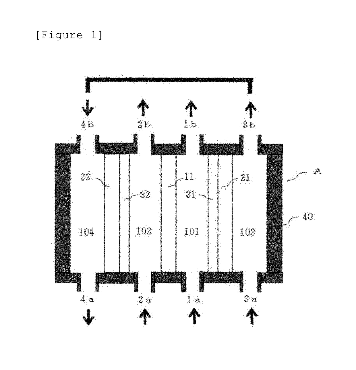
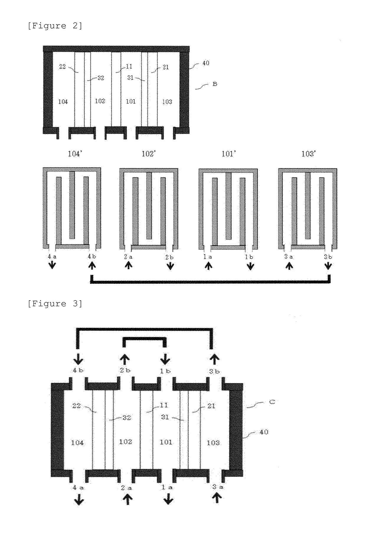
The present invention relates to an apparatus for generating electrolyzed water, which generates hydrogen water comprising hydrogen molecules in a high concentration. Two sheets of porous cathode plates each provided on the surface thereof with an ion-exchange membrane are provided across an anode plate so as for the ion-exchange membranes to face the anode plate and so as to form a space allowing water to flow therethrough, between the anode plate and each of the ion-exchange membranes, and thus four electrolysis chambers are formed. Thus, here is provided an apparatus for generating electrolyzed water in which there are formed a first water path and a second water path to feed water respectively to the first electrolysis chamber and the second electrolysis chamber formed between the anode plate and the cathode plates, and a third water path to feed water to either of the third electrolysis chamber and the fourth electrolysis chamber formed on the sides of the cathode plates on the other side of the anode plate and to feed the treated water passing through the electrolysis chamber to the other electrolysis chamber.

Description

TECHNICAL FIELD[0001]The present invention relates to an apparatus for generating an electrolyzed water, which generates hydrogen water comprising hydrogen molecules in a high concentration.BACKGROUND ART[0002]Recently, the efficacy for health and the medical efficacy of a water (hydrogen water) comprising hydrogen molecules in a large amount have been attracting attention. As the method for generating hydrogen water, there have been known, for example, a method based on the electrolysis of water and a method dissolving hydrogen gas in water; various apparatuses for generating electrolyzed water have been proposed as the apparatus for generating hydrogen water by electrolysis. For example, there has been proposed an electrolysis apparatus for generating an electrolyzed negative electrode water comprising hydrogen gas (H2) and reducing ions wherein an electrolyzer having a porous diaphragm is used, electrodes, namely a positive electrode and a negative electrode are inserted into an ...

Claims


Application Information

Patent Timeline
IPC IPC(8): C25B1/06C02F1/461C25B9/23
CPCC02F1/46109C02F2001/46195C25B1/06C02F1/4618C02F2001/46161C02F2001/46185C02F2001/4619C02F2201/4611C02F2201/46115C02F2201/46155C02F2201/46185C02F2301/028Y02E60/36C25B11/00C02F1/4676C02F2201/4618C25B9/23C25B1/04
Inventor GOHDA, TOSHIHISA
Owner LEE JAE YONG
Learn More