Light guide, line-illuminating device, and image-scanning device

a technology of image scanning and light guide, which is applied in the direction of waveguides, printing, instruments, etc., can solve the problems of non-uniform light amount and flat surface that rarely serves as reflecting surfa

Inactive Publication Date: 2006-07-11
NIPPON SHEET GLASS CO LTD
View PDF17 Cites 34 Cited by
  • Summary
  • Abstract
  • Description
  • Claims
  • Application Information

AI Technical Summary

Benefits of technology

[0015]With the provision of curved reflecting surfaces such as a spherical surface as a light-reflecting portion, even small displacement of the incident angle of light on the light-reflecting portion changes the reflection angle greatly, so that the intensity of emitted light can be uniform. In addition, by employing a light-reflecting portion rather than a light scattering portion, the direction of the reflected light can be controlled. Specifically, in the case of the light scattering pattern as disclosed in Patent Document 1, the luminous flux of light emitted from the light-emitting surface becomes wide when it is seen from the end surface of the light guide, and thereby the light amount becomes non-uniform. However, in the case of the tubular concave surfaces, the direction of emitted light can be controlled.

Problems solved by technology

Specifically, in the case of the light scattering pattern as disclosed in Patent Document 1, the luminous flux of light emitted from the light-emitting surface becomes wide when it is seen from the end surface of the light guide, and thereby the light amount becomes non-uniform.
In particular, in a case where a flat surface is provided between the side surface and the bottom surface of a light guide by C-chamfering, the flat surface hardly ever serves as a reflecting surface with respect to the light-emitting surface.

Method used


Image

  • Light guide, line-illuminating device, and image-scanning device
  • Light guide, line-illuminating device, and image-scanning device
  • Light guide, line-illuminating device, and image-scanning device

Examples


embodiment 2

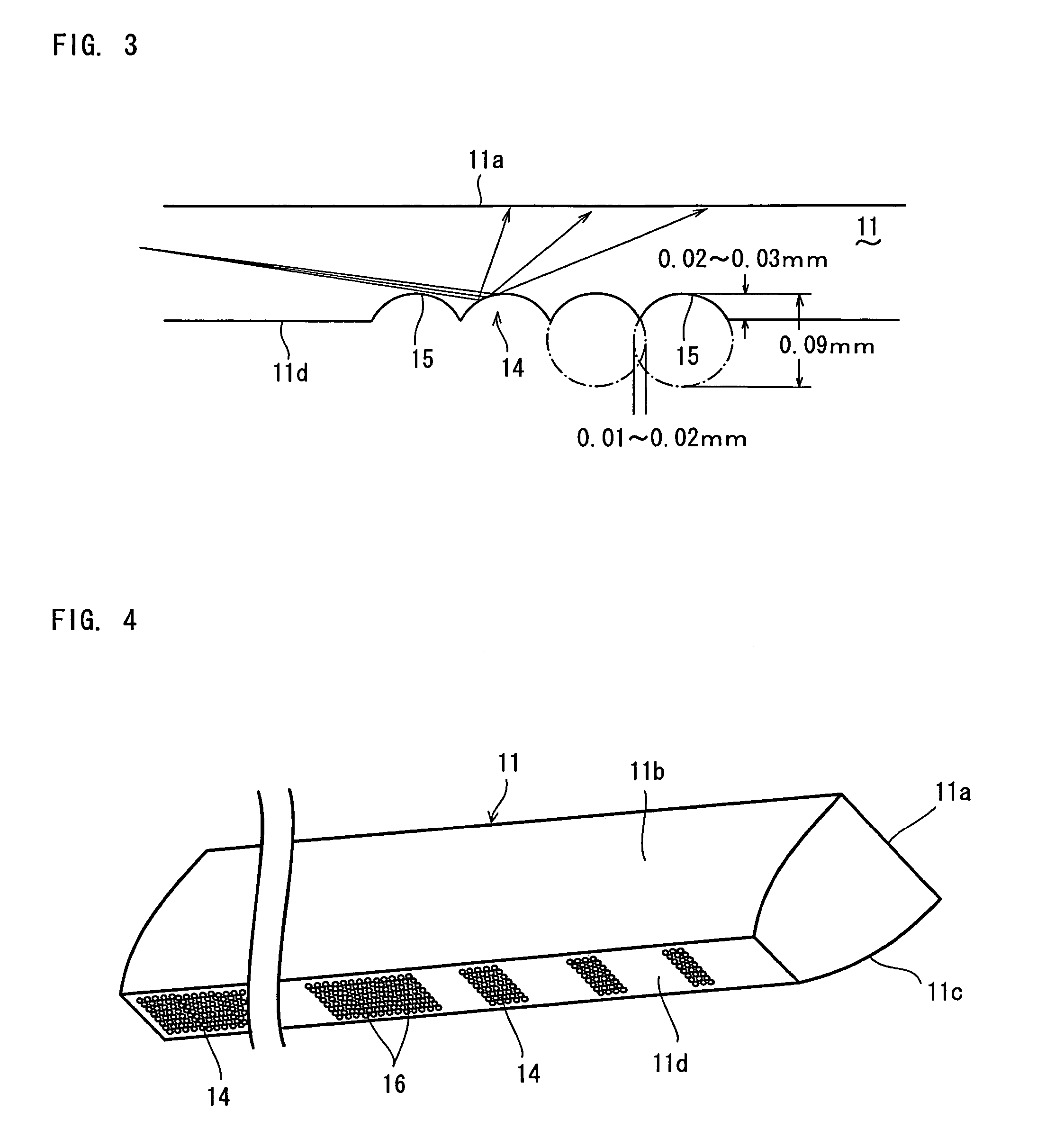
[0044]FIG. 4 is a perspective view showing another embodiment (Embodiment 2) of the light guide, and FIG. 5 is an enlarged view of a portion of FIG. 4. In this embodiment, each of the forming areas of the light-reflecting portion 14 is comprised of fine spherical concave surfaces 16 which are formed densely and continuously, and both of the side surfaces 11b and 11c are formed as a curved surface. As for the curved surface, an elliptic surface or a parabolic surface may be possible, and the curvature may be different between both of the side surfaces so as to increase the depth of focus.

[0045]The cross-sectional shape of the spherical concave surface 16 is an arc having a depth of 0.02–0.03 mm which is obtained by superposing circles having a diameter of 0.09 mm in the range of 0.01–0.02 mm in the same manner as the tubular concave surface 15. Again, the depth of the arc is smaller than the radius of the circle.

embodiment 1

[0046]In the case of using the fine spherical concave surface 16 as the light-reflecting portion 14, light from the end surface is reflected toward both of the side surfaces 11b and 11c as well as the upper surface 11a as a light-emitting surface. Therefore, both of the side surfaces 11b and 11c should be a curved surface rather than a flat surface such as Embodiment 1, so that both of the side surfaces 11b and 11c can serve as a reflecting surface.

[0047]FIG. 6 is a perspective view showing another embodiment of the light guide. In this embodiment, tubular concave surfaces 15 are formed continuously in the main-scanning direction to form the light-reflecting portion 14, and the width is reduced on the side of the light source unit 13, so that the amount of reflected light can be uniform.

[0048]Also, in the embodiment shown in FIG. 6, a recessed portion 17 is provided in the end surface of the light guide 11, and the light source unit 13 is set in the recessed portion 17. As a result ...


PUM


Abstract

A light guide, a line-illuminating device, and an image-scanning device are provided which are excellent in uniformity of the light amount. A light-reflecting portion comprised of tubular concave surfaces becomes a reflecting surface having tubular convex surfaces when seen from the inside of the light guide. With such structure, even when the incident angle of light from a light source unit slightly displaces, the reflection angle in the tubular convex surfaces significantly changes. In an irregular surface having a triangular shape, as in a conventional example, the incident angle becomes almost uniform in the area far from the light source unit, and thereby the reflection angle also becomes uniform. Consequently, it is difficult to achieve uniform reflection in the main-scanning direction. However, with the tubular concave surfaces, light is reflected uniformly toward the upper surface as a light-emitting surface.

Description

BACKGROUND OF THE INVENTION[0001]1. Field of the Invention[0002]The present invention relates to a light guide, a line-illuminating device, and a contact-type or reduction-type image-scanning device (image sensor) in which the line-illuminating device is incorporated.[0003]2. Description of the Background Art[0004]An image-scanning device for a facsimile machine, a copying machine, an image scanner or the like is provided with a line-illuminating device for linearly illuminating a document surface along a main scanning field. In the line-illuminating device, light is introduced into an end surface of a bar-shaped or plate-shaped transparent light guide, reflected on the internal surfaces, and emitted from a light-emitting surface.[0005]Since a light-emitting element such as an LED is provided on one end or both ends of the light guide of the line-illuminating device, the amount of emitted light is greater toward the end, and the light intensity is non-uniform in the main-scanning di...

Claims


Application Information

Patent Timeline
Patent Type & Authority Patents(United States)
IPC IPC(8): G02B6/00F21S2/00F21V8/00F21Y101/02G02B6/10G03B27/54H04N1/028H04N1/04
CPCG02B6/0038H04N1/02815H04N1/02885H04N1/02835Y10S385/901H04N1/04
Inventor NEMOTO, HIROYUKIIWASE, HIROHIKOTAKEUCHI, HIDEMITSUKISHIMOTO, TAKASHI
Owner NIPPON SHEET GLASS CO LTD
Why Eureka
Try Eureka