Optical guide and surface light emitting apparatus using the same

Active Publication Date: 2006-08-17
NICHIA CORP
View PDF27 Cites 34 Cited by
  • Summary
  • Abstract
  • Description
  • Claims
  • Application Information

AI Technical Summary

Benefits of technology

[0039] The optical guide of the present invention makes it possible to improve the uniformity o

Problems solved by technology

Thus the optical guides of the prior art fail to e

Method used


Image

  • Optical guide and surface light emitting apparatus using the same
  • Optical guide and surface light emitting apparatus using the same
  • Optical guide and surface light emitting apparatus using the same

Examples


first embodiment

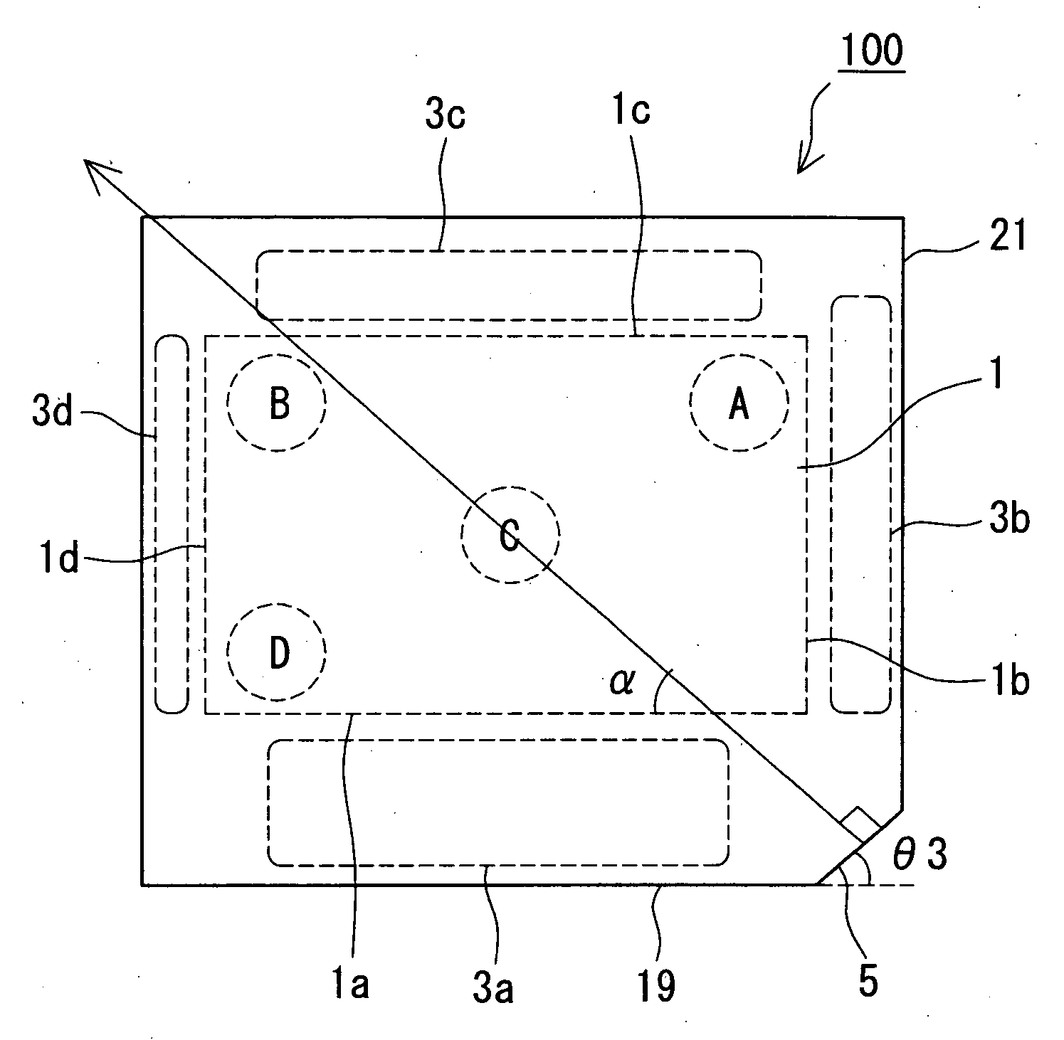
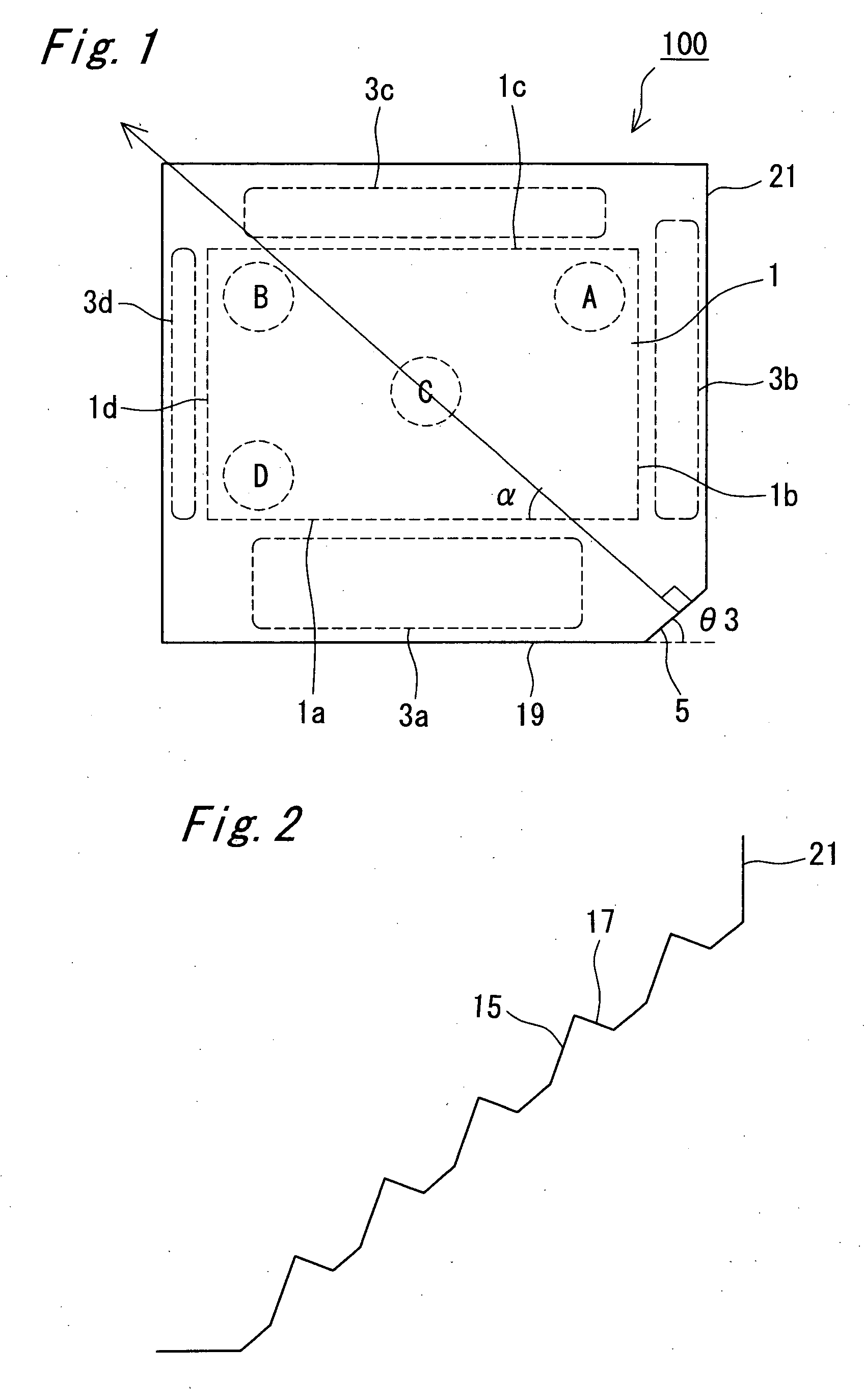
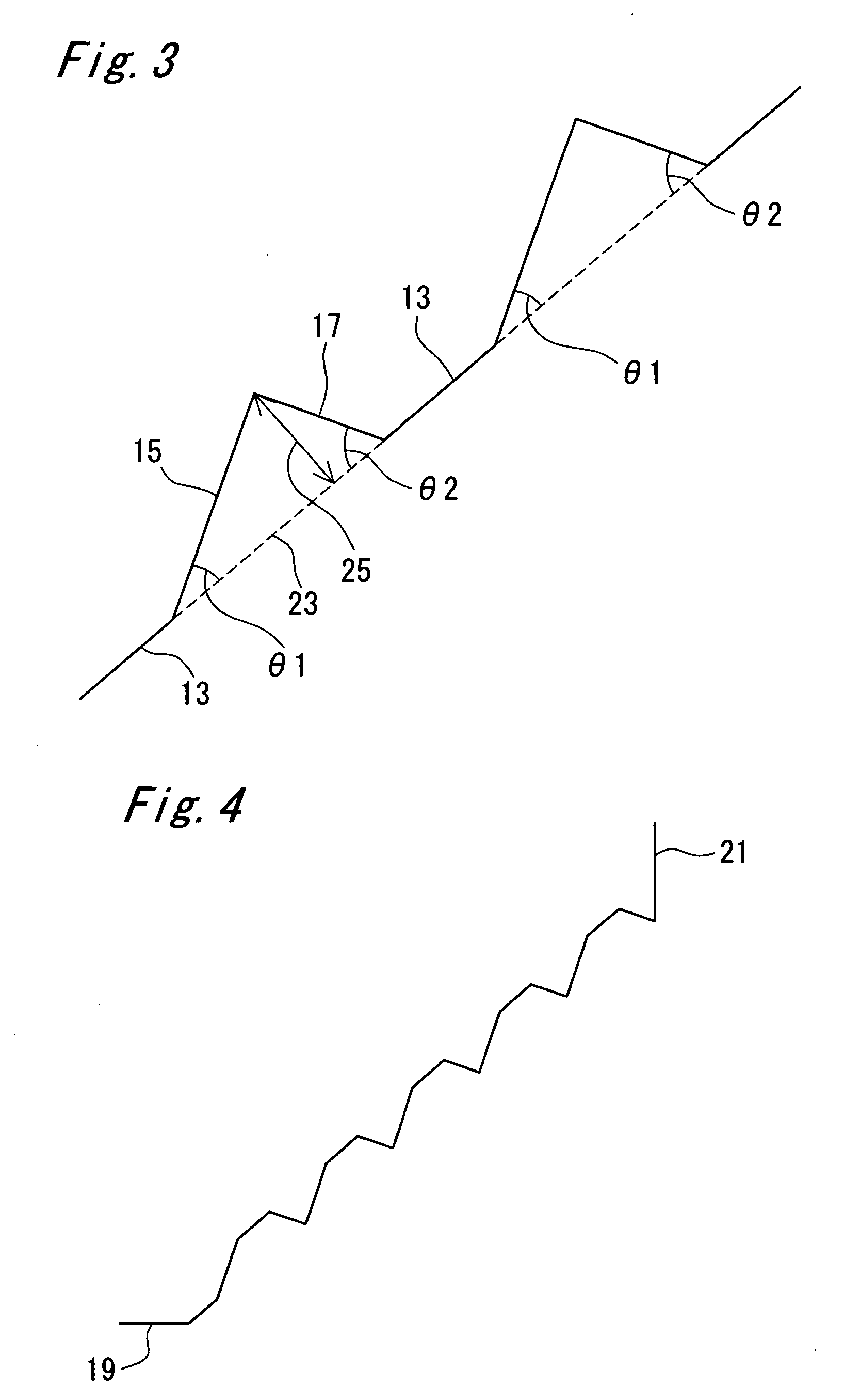
[0093]FIG. 1 is a top view of an optical guide 100 of the first embodiment viewed in the direction of light emerging surface. FIGS. 2 through 4 are enlarged top views showing a corner 5 of the optical guide 100 of this embodiment. FIG. 3, in particular, is an enlarged top view of notch located in the corner shown in FIG. 2. FIG. 7 is a perspective view of the optical guide 100 of this embodiment. FIGS. 8 through 11 are enlarged perspective views of notches having various forms provided at the corner of the optical guide 100 of this embodiment. FIG. 3 is an enlarged view of the notch shown in FIG. 8 viewed in the direction perpendicular to the light emerging surface.

[0094] The optical guide 100 of the first embodiment that includes an effective light emitting region 1 of rectangular shape that has a long side and a short side in the light emerging surface, the light emerging surface being constituted by forming the notches in an inclined surface obtained by obliquely cutting off at ...

second embodiment

[0133] The optical guide of the second embodiment has the light emerging surface formed to have the circumferential configuration of trapezoidal shape (FIG. 14 through FIG. 24).

[0134] In the optical guide of the second embodiment, corners through which light from the light emitting diode is introduced is constituted similarly to the first embodiment, so that the light emitting surfaces of the light emitting diode face at a predetermined angle. In the second embodiment, the light emerging surface of the optical guide is not required to have the exact shape of trapezoid. By forming the light emerging surface in trapezoidal shape, it is made possible to increase the efficiency of light emission from the effective light emitting region 1 of the optical guide. That is, according to the second embodiment, portion of light that has been wasted by escaping from the non-observing region 3 can be guided into the effective light emitting region 1. The optical guide of the second embodiment wi...

third embodiment

[0146]FIG. 36 is a top view of the optical guide 300 of the third embodiment viewed from the side of the light emerging surface. The optical guide 300 of the third embodiment has the effective light emitting region 1 having longer side and shorter side included in the light emerging surface similarly to the first embodiment, but has the light introducing section of structure different from that of the first embodiment. That is, in the optical guide of the third embodiment, the light introducing section 305 that includes semi-circular notch formed in at least one corner is provided instead of the light introducing section that includes the notch, wherein uniform light emission in the effective light emitting region 1 is maintained by setting the diameter and center angle of the semi-circular shape of the notch and the direction of the center axis of light distribution in accordance to the directivity of the light emitting diode.

[0147] A method for setting the diameter and center ang...


PUM


Abstract

A light emitting apparatus that is capable of emitting light with uniform intensity and high luminance are provided. The first optical guide comprises a first principal surface that has an effective light emitting region of substantially rectangular shape surrounded by first through fourth sides and a second principal surface that opposes the first principal surface, wherein the circumferential side face of the optical guide includes first through fourth side faces disposed along the first through fourth sides, respectively, and a light introducing section, disposed at the corner interposed between the first and second side faces, with an angle of inclination from the first side face that is determined so that center axis of light distribution intersects one of the first through fourth sides and divides the area of the effective light emitting region into two equal parts.

Description

TECHNICAL FIELD [0001] The present invention relates to an optical guide that lets incident light emerge from a predetermined light emerging surface, and a surface light emitting apparatus that combines the optical guide and a point light source. BACKGROUND ART [0002] In recent years surface light emitting apparatuses have been used as the backlight of liquid crystal display, the surface light emitting apparatus having such a constitution as light emitted by a light emitting diode enters a plate-shaped optical guide through a side face thereof and emerges from a principal surface of the optical guide in surface emitting operation. [0003] In the surface light emitting apparatus, light emitted by the light emitting diode is introduced into a plate-shaped optical guide through a side face thereof and is emitted through a predetermined light emission observing surface by making use of reflection in the optical guide. The light emitting diode used as the light source is typically mounted...

Claims


Application Information

Patent Timeline
IPC IPC(8): F21V7/04
CPCG02B6/002G02B6/0021G02B6/003G02B6/0068H01L33/54H01L2224/48091H01L2924/181H01L2224/0603H01L2924/00014H01L2924/00012
Inventor TAMURA, YUUKIOMURA, JUNICHIMORI, TAKU
Owner NICHIA CORP
Why Eureka
Try Eureka