Method for producing a three-dimensional fiber reinforced ring frame component

a three-dimensional fiber and ring frame technology, applied in the direction of braids, other domestic articles, transportation and packaging, etc., can solve the problems of low mechanical characteristics of short fiber prepreg, uneconomical sustainable production conditions, and inability to produce economically. achieve the effect of ensuring the stability of the finished frame, and precise positioning of the substrate and ribbon material

Inactive Publication Date: 2003-12-04
INST FUER VERBUNDWERKSTOFFE GMBH +1
View PDF5 Cites 37 Cited by
  • Summary
  • Abstract
  • Description
  • Claims
  • Application Information

AI Technical Summary

Benefits of technology

[0006] to provide a carbon fiber composite construction method that is significantly more economical compared to such conventional methods;
[0018] It is a special advantage of the invention that the prepreg and final product can be produced economically by mass production steps such as sewing or stitching the deformable fiber ribbon material to the substrate along a folding line which assures a precise positioning of the substrate and ribbon material relative to each other. The stitching or seam also permits the radially inner section of the ribbon material to initially fold to maintain the desired uniform fiber orientation and fiber density distribution. Such a prepreg can be inserted into a molding tool to be impregnated for example by a resin injection technique. The uniformly distributed fiber orientation and density distribution achieved according to the invention is also an important advantage of the invention because it assures uniform strength characteristics of the finished frame component throughout the volume of the finished component. These uniform strength characteristics apply to the section that remains flat and in parallel to the substrate and to the folded out flange section. The section that remains flat and in parallel to the substrate may be easily provided with a row of holes for riveting the frame component to the body of an aircraft. Yet another advantage is seen in that the textile ribbon material or woven fabric or circularly woven hose material is readily available as mass produced items that can be purchased without problems in any desired quantity. It has been found that the homogeneity in the fiber distribution and fiber densities throughout the volume of the frame structure according to the invention is particularly achieved by fiber fabrics that have been sheared as compared to other fabric materials and fabric productions that do not use circular hose weaving.

Problems solved by technology

However, such a short fiber prepreg has low mechanical characteristics and adds to the weight of the finished component.
These carbon fiber composite processes or technologies achieve the required mechanical characteristics, however, the production under economically sustainable conditions has not been possible heretofore.
Thus, the disadvantages of conventional fiber composite constructions are seen in the high effort and expense for manual operations and in the inadequate assurance that quality requirements are satisfied.
However, substantial difficulties are encountered in the large scale use of fibers which are assembled in the so-called tailored fiber placement methods, whereby the fibers are laid down and sewn together.
The same difficulties are encountered when using spirally woven fabrics which are used in order to form reinforcements around a hole in the structural component.
These difficulties are seen particularly in the expensive and involved production of the semifinished products and generally in the working of the fibers.
In connection with the production of spirally woven fabrics, particularly the oval geometry entails substantial limitations with regard to the availability of such fabrics due to the complexity and the comparably expensive semifinished product manufacture.
The tailored fiber placement method is at present still not suitable for a large scale production due to its low fiber depositing or layering speeds.
Another disadvantage of the tailored fiber placement method is seen in that substantial inhomogenities in the fiber distribution in the body of the layered fibers result when these layered fibers are shaped into a curved structure.

Method used


Image

  • Method for producing a three-dimensional fiber reinforced ring frame component
  • Method for producing a three-dimensional fiber reinforced ring frame component
  • Method for producing a three-dimensional fiber reinforced ring frame component

Examples


Embodiment Construction

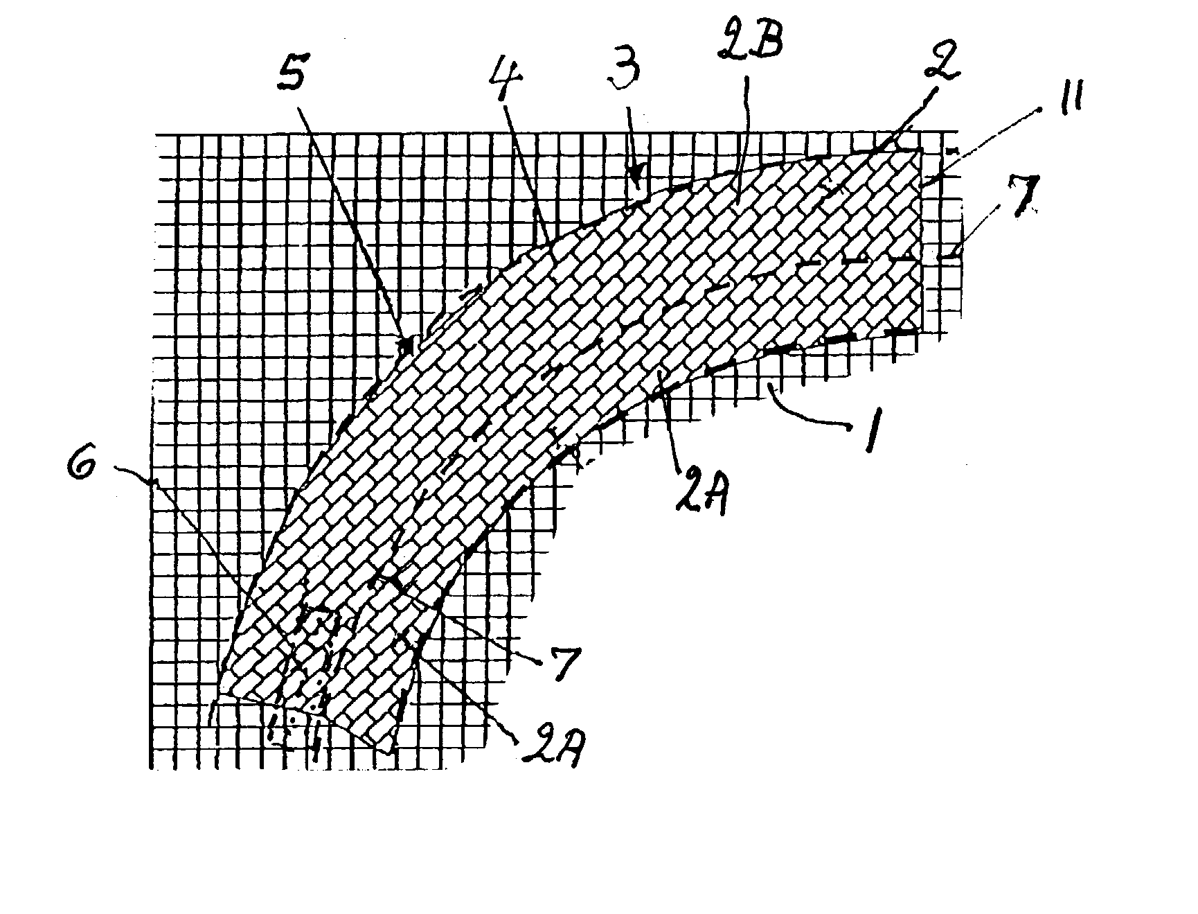
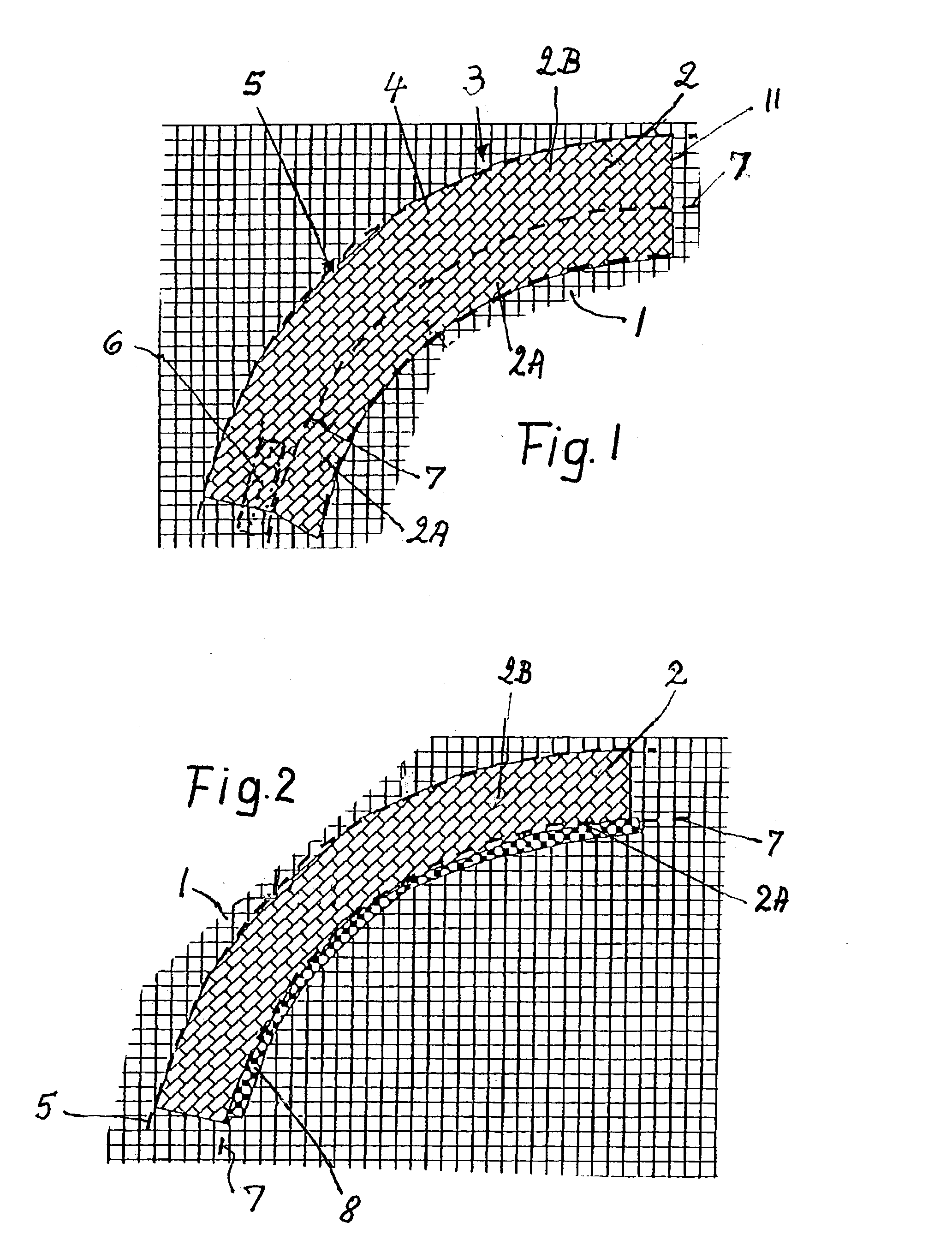
[0024] FIG. 1 shows a carrier material 1 cut off from a woven fiber mesh fabric such as glass fiber material or carbon fiber material. The shown square fiber orientation is preferred, but other fiber mesh orientations are also feasible, provided the strength requirements are satisfied. The carrier material 1 defines a plane that coincides or extends in parallel with the plane of the drawing sheet. A drapable or deformable fiber material 2 preferably in ribbon form is secured to the substrate 1 by sewing or stitching along a stitching line 7 that also becomes a folding line as will be described in more detail below. The deformable or drapable fiber material 2 is preferably a circularly woven hose material that can be flattened down in part and draped or folded in part without disturbing the given fiber orientation of such a fiber fabric. It will be noted that the stitching or folding line 7 divides the ribbon material into two sections, namely a radially inner section 2A and a radial...


PUM

PropertyMeasurementUnit
structureaaaaaaaaaa
sizeaaaaaaaaaa
angleaaaaaaaaaa

Abstract

A closed ring fiber reinforced frame structure is produced by first preparing a prepreg. A section of the prepreg is formed into a flange preferably after impregnation by folding the flange section along a folding line. The folding line is formed by securing a deformable or drapable fiber ribbon material, for example by sewing or stitching to a carrier substrate which is preferably also a fiber material. The sewing seam or stitching line becomes the folding line. The ribbon material is so secured to the carrier substrate that the fiber orientation of the ribbon material is uniformly distributed all around a ring component that is formed of the ribbon material on the substrate. The impregnated ring component with its substrate is then cured after the folding of the flange to complete the ring frame structure.

Description

PRIORITY CLAIM[0001] This application is based on and claims the priority under 35 U.S.C. .sctn.119 of German Patent Applications 102 10 086.1, filed on Mar. 8, 2002 and 102 51 579.1, filed on Jun. 11, 2002, the entire disclosure of which is incorporated herein by reference.[0002] The invention relates to a method for producing a fiber prepreg that is then formed and cured to produce a fiber reinforced ring frame component particularly for aircraft windows. The fiber reinforced ring frame component is preferably round or oval and has a flange that extends all along the inner or outer circumference of the ring frame component.BACKGROUND INFORMATION[0003] Conventional window frames for jumbo aircraft are produced of aluminum sheet metal by die stamping operations, particularly for reasons of economy. However, due to the smaller density of carbon fiber reinforced composite materials which have a mechanical strength or stiffness similar to that of aluminum, one can expect to achieve a s...

Claims


Application Information

Patent Timeline
Patent Type & Authority Applications(United States)
IPC IPC(8): B29C70/22B29C70/30B29C70/54B64C1/14D04C1/06D04H13/00
CPCB29C70/222B29C70/30B29C70/543B64C1/1484D04C1/06Y02T50/433D04H1/4242D04H1/44D04H13/00D10B2505/02D04H1/4218B29L2031/005Y02T50/40
Inventor EDELMANN, KLAUSWEIMER, CHRISTIAN
Owner INST FUER VERBUNDWERKSTOFFE GMBH
Why Eureka
Try Eureka