Line-illuminating device and image sensor

a technology of illumination device and image sensor, which is applied in the direction of fixed installation, lighting and heating apparatus, instruments, etc., can solve the problems of large attenuation of light intensity in the light emitting direction, uneven intensity of illumination light in the main scanning direction, and uneven intensity of illumination ligh

Inactive Publication Date: 2006-10-24
NIPPON SHEET GLASS CO LTD
View PDF7 Cites 36 Cited by
  • Summary
  • Abstract
  • Description
  • Claims
  • Application Information

AI Technical Summary

Benefits of technology

[0011]It is therefore an object of the present invention to provide an improved line-illuminating device of which the intensity of light in a main scanning direction is uniform and in which severe accuracy is not required when being incorporated in a contact-type image sensor.
[0014]In this manner, since the light-scattering pattern is formed, on the side face including the short sides where a surface sink is not easily produced, by printing or other methods, it is possible to make the intensity of illuminating light in the main scanning direction uniform.
[0015]The whole area of the side face facing the face on which the light scattering pattern is provided can be used as the light-emitting surface. Accordingly, it is possible to make the area of the light-emitting surface larger than before, to control the attenuation of light intensity, and to improve the light distribution characteristics. Further, severe positioning accuracy is not required when the line-illuminating device is incorporated.
[0016]By providing the light source on the normal line of the light-scattering pattern, it is possible to make the light scattering efficiency maximum. As a result, it is possible to make the light emitting from the opposite side face maximum.

Problems solved by technology

In this manner, a pattern shape is different from the intended shape and as a result, the intensity of illuminating light in a main scanning direction may be uneven.
In the case where the notch is provided to print the light-scattering pattern as described in the embodiment of Japanese Patent No. 3083092, it is troublesome because printing itself is effected on a surface which is not parallel with the side face of the light guide.
Further, uneven intensity of illuminating light is readily obtained because a surface sink is easily produced on that surface.
As a result, attenuation of light intensity in the light emitting direction becomes large and light distribution characteristics (i.e., the ratio of optical power in a predetermined position to optical power in a position out of the predetermined position) become worse.
In this manner, severe positioning accuracy is required when the line-illuminating device is incorporated with the contact-type image sensor.

Method used


Image

  • Line-illuminating device and image sensor
  • Line-illuminating device and image sensor
  • Line-illuminating device and image sensor

Examples


Embodiment Construction

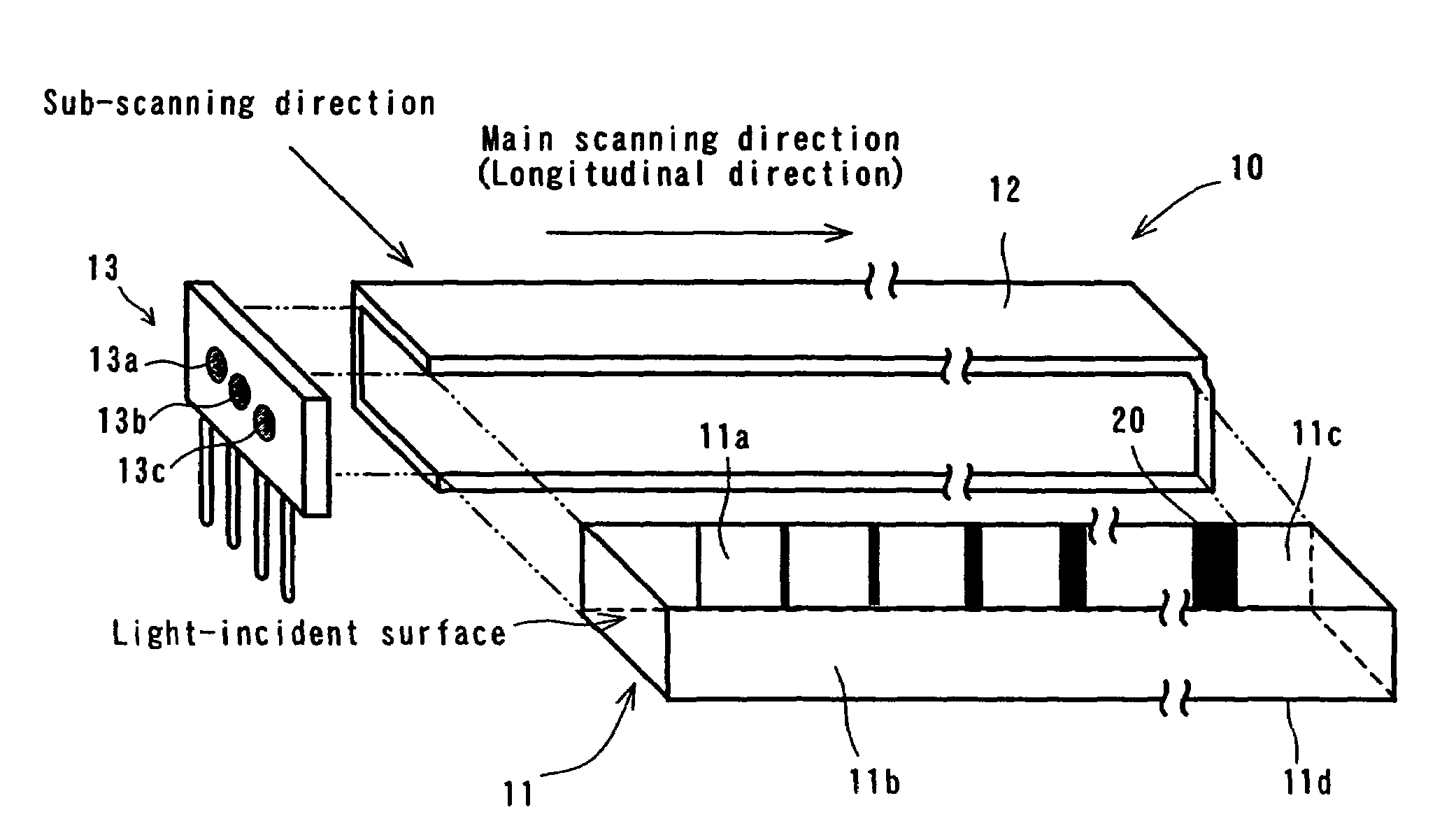
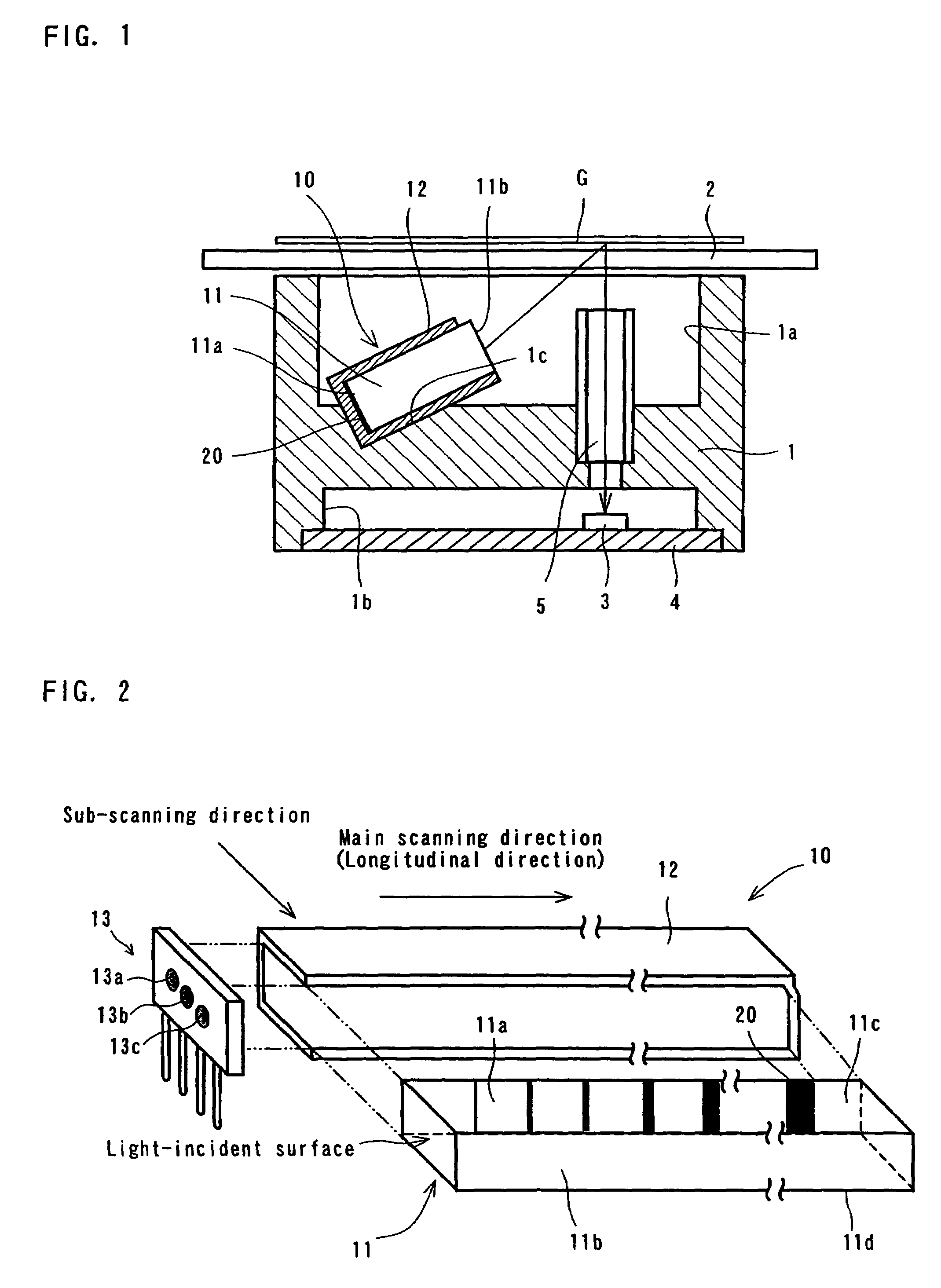
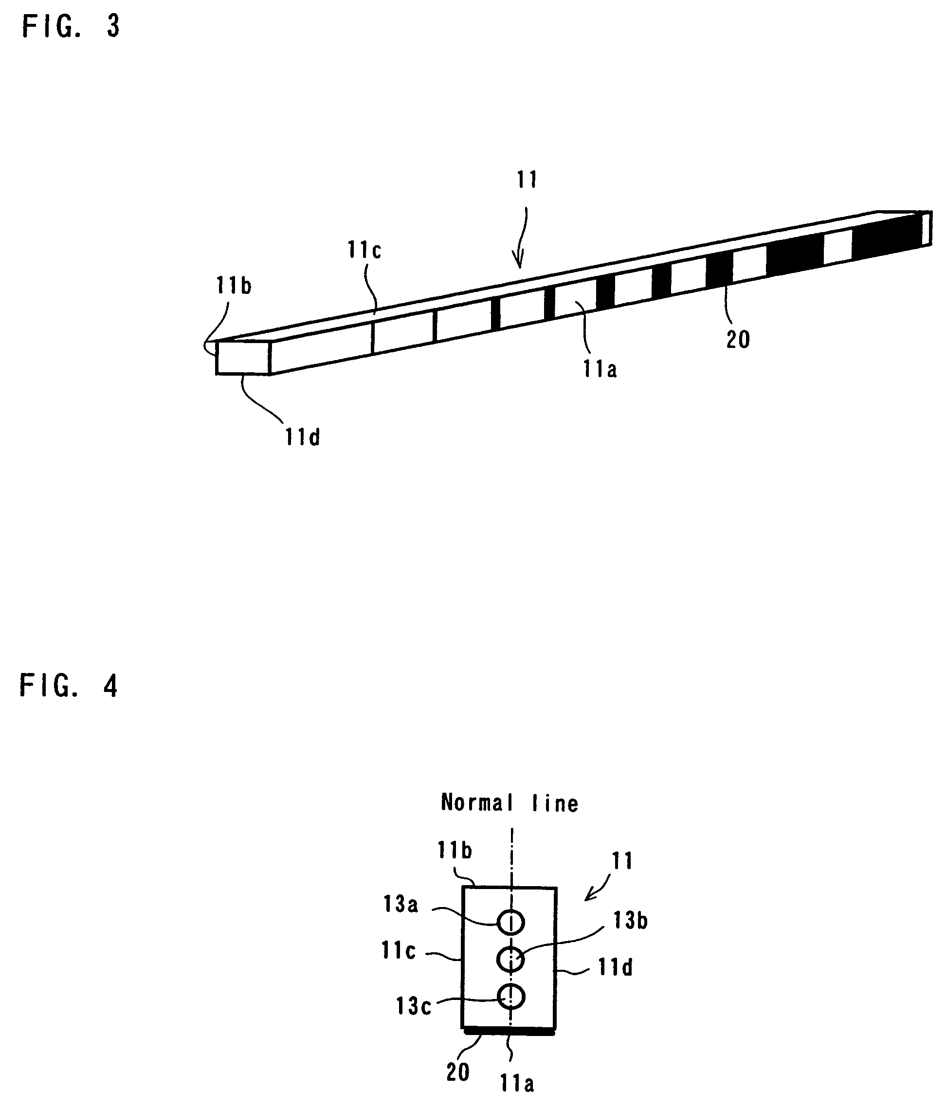
[0027]Preferred embodiments of the present invention will now be described with reference to the accompanying drawings. FIG. 1 is a cross-sectional view of an image sensor incorporated with a line-illuminating device according to the present invention. FIG. 2 is an exploded perspective view of the line-illuminating device. FIG. 3 is a perspective view showing one example of a light-scattering pattern formed on the back side of a light guide and FIG. 4 is an end view showing the relationship between the light-scattering pattern and a light-emitting unit.

[0028]The image sensor is provided, in which a frame 1 is provided with depressed portions 1a, 1b and the upper surface of the depressed portion 1a is covered by a glass plate 2 for mounting a document G thereon. The depressed portion 1a is further provided therein with a depressed portion 1c for fixedly securing a line-illuminating device 10 therein at an angle (between 0 and 45 degrees relative to the horizontal plane). Provided in ...


PUM


Abstract

A light guide 11 of a rectangular cross-section has side faces 11a, 11b including short sides in the longitudinal direction of which one side face 11a is provided with a light-scattering pattern 20, formed by screen-printing in white paint, for scattering the light incident to the light guide 11. The other side face 11b facing the side face 11a is exposed from a casing 12 to serve as a light-emitting surface. In the present embodiment, it is possible to secure a sufficient amount of light because the whole area of the side face is used as the light-emitting surface. The remaining side faces 11c, 11d of the light guide 11 are side faces including the long sides. Since the side faces 11c, 11d easily produce a surface sink during molding, neither the light-scattering pattern 20 nor the light-emitting surface is provided thereon.

Description

BACKGROUND OF THE INVENTION[0001]1. Field of the Invention[0002]The present invention relates to an illuminating device using a bar-shaped light guide and a contact-type image sensor incorporated with the illuminating device.[0003]2. Description of the Prior Art[0004]A contact-type image sensor is used as a device for reading a document in a facsimile machine, a copying machine, an image scanner device and the like. The contact-type image sensor is provided with a line-illuminating device for linearly illuminating a document surface along the main scanning zone.[0005]A line-illuminating device using a light guide is known. For example, Japanese Patent No. 3083092 discloses a line-illuminating device in which a light-emitting unit is provided on one end of the light guide and a light-scattering pattern is formed along the longitudinal direction of the light guide to spread and reflect the light emitted from the light-emitting unit. A plurality of light sources (i.e., LEDs) of the lig...

Claims


Application Information

Patent Timeline
Patent Type & Authority Patents(United States)
IPC IPC(8): F21V8/00F21S8/04F21V7/04F21V11/00F21Y101/02G02B5/02G02B6/00H01J5/16H01P5/00H04N1/028H04N1/04
CPCG02B5/0221H04N1/0289H04N1/02835G02B6/0038G02B6/0058
Inventor UEMURA, YOSHIYUKIKISHIMOTO, TAKASHIFUJIMURA, KOZOSAITO, TOMIHISATAGUCHI, MASAFUMI
Owner NIPPON SHEET GLASS CO LTD
Why Eureka
Try Eureka