
Line-illuminating device and image sensor

Inactive Publication Date: 2005-09-08
NIPPON SHEET GLASS CO LTD
View PDF5 Cites 19 Cited by
  • Summary
  • Abstract
  • Description
  • Claims
  • Application Information

AI Technical Summary

Benefits of technology

[0011] It is therefore an object of the present invention to provide an improved line-illuminating device of which the intensity of light in a main scanning direction is uniform and in which severe accuracy is not required when being incorporated in a contact-type image sensor.
[0014] In this manner, since the light-scattering pattern is formed, on the side face including the short sides where a surface sink is not easily produced, by printing or other methods, it is possible to make the intensity of illuminating light in the main scanning direction uniform.
[0015] The whole area of the side face facing the face on which the light scattering pattern is provided can be used as the light-emitting surface. Accordingly, it is possible to make the area of the light-emitting surface larger than before, to control the attenuation of light intensity, and to improve the light distribution characteristics. Further, severe positioning accuracy is not required when the line-illuminating device is incorporated.
[0016] By providing the light source on the normal line of the light-scattering pattern, it is possible to make the light scattering efficiency maximum. As a result, it is possible to make the light emitting from the opposite side face maximum.

Problems solved by technology

In this manner, a pattern shape is different from the intended shape and as a result, the intensity of illuminating light in a main scanning direction may be uneven.
In the case where the notch is provided to print the light-scattering pattern as described in the embodiment of Japanese Patent No. 3083092, it is troublesome because printing itself is effected on a surface which is not parallel with the side face of the light guide.
Further, uneven intensity of illuminating light is readily obtained because a surface sink is easily produced on that surface.
As a result, attenuation of light intensity in the light emitting direction becomes large and light distribution characteristics (i.e., the ratio of optical power in a predetermined position to optical power in a position out of the predetermined position) become worse.
In this manner, severe positioning accuracy is required when the line-illuminating device is incorporated with the contact-type image sensor.

Method used


Image

  • Line-illuminating device and image sensor
  • Line-illuminating device and image sensor
  • Line-illuminating device and image sensor

Examples


Embodiment Construction

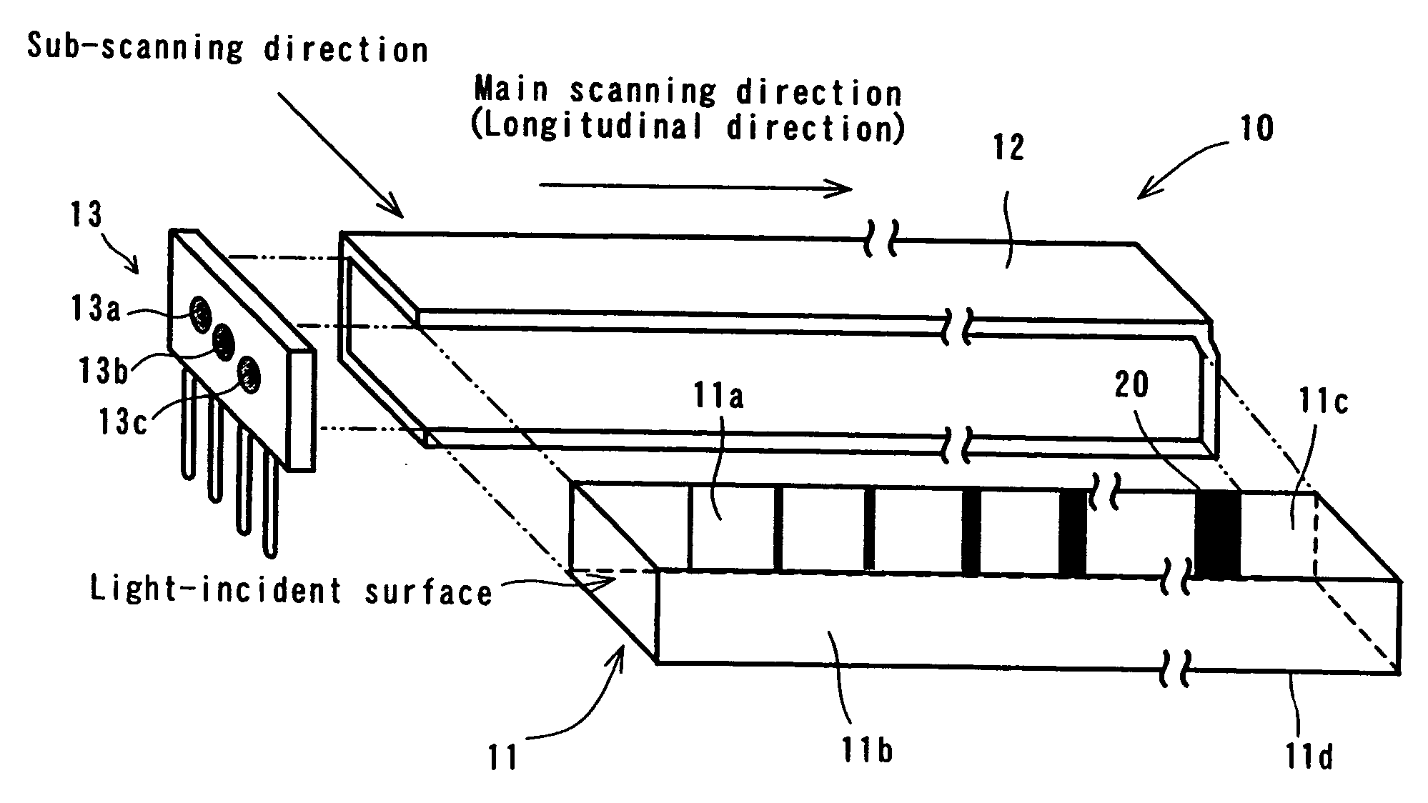
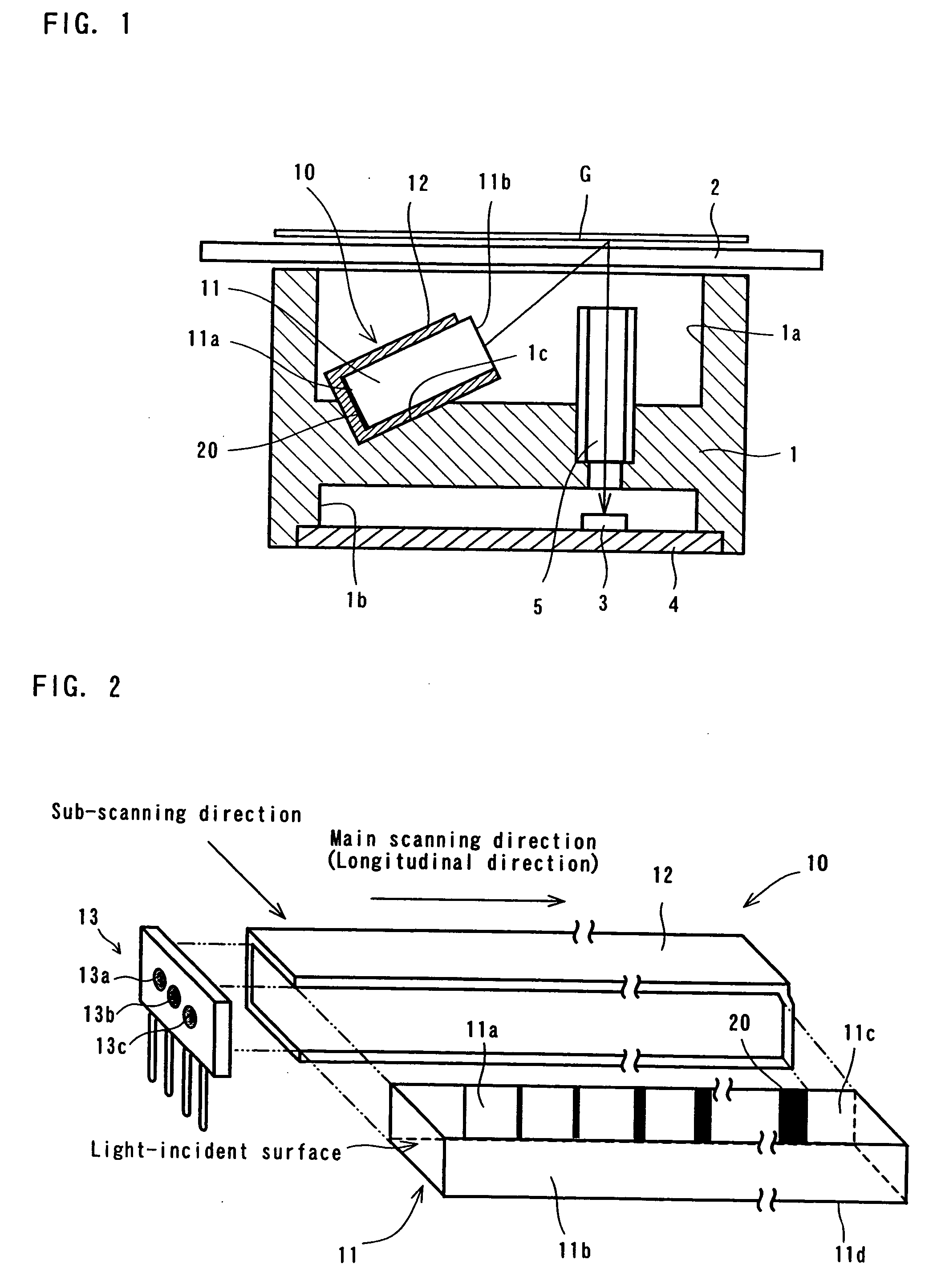
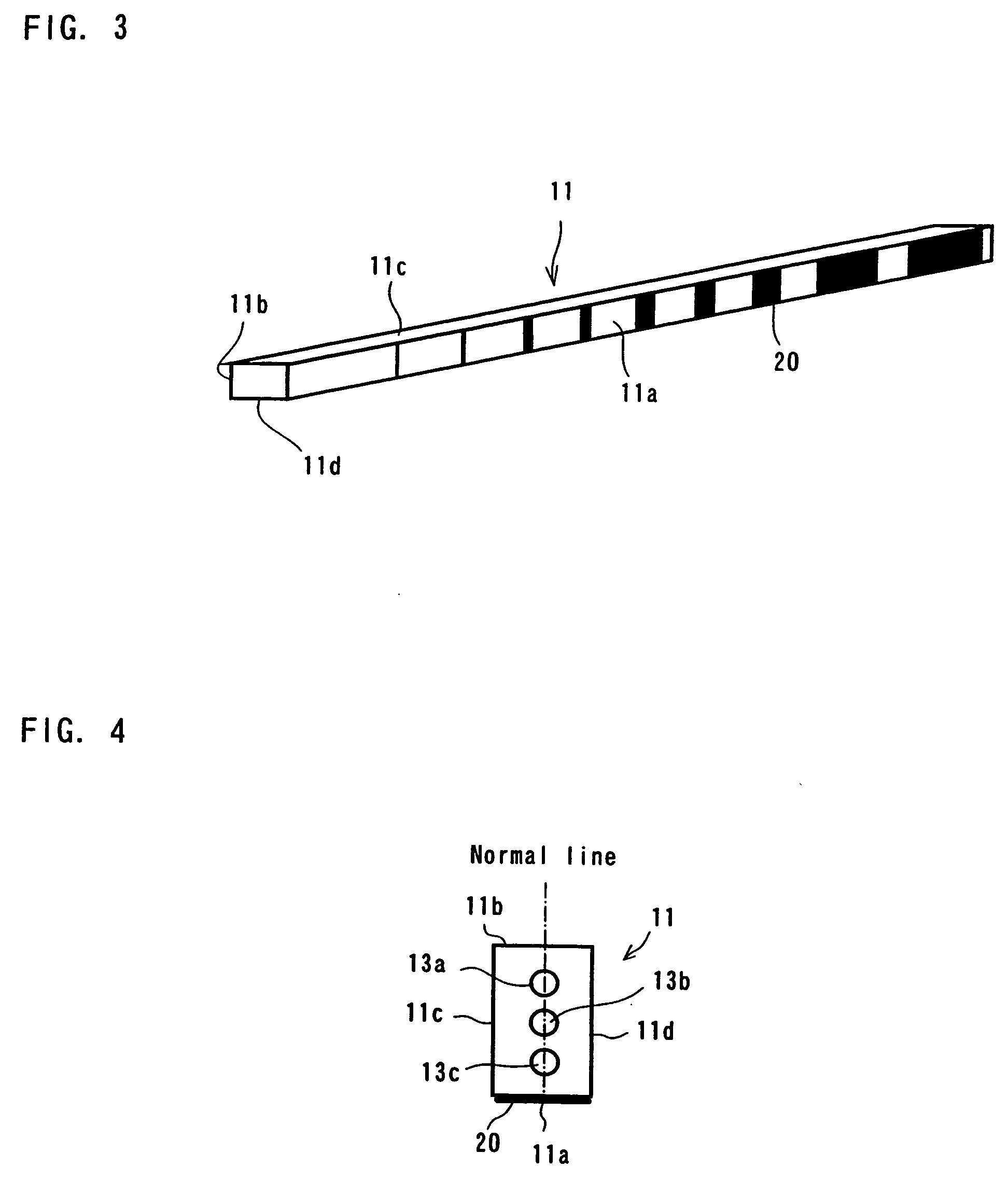
[0027] Preferred embodiments of the present invention will now be described with reference to the accompanying drawings. FIG. 1 is a cross-sectional view of an image sensor incorporated with a line-illuminating device according to the present invention. FIG. 2 is an exploded perspective view of the line-illuminating device. FIG. 3 is a perspective view showing one example of a light-scattering pattern formed on the back side of a light guide and FIG. 4 is an end view showing the relationship between the light-scattering pattern and a light-emitting unit.

[0028] The image sensor is provided, in which a frame 1 is provided with depressed portions 1a, 1b and the upper surface of the depressed portion 1a is covered by a glass plate 2 for mounting a document G thereon. The depressed portion 1a is further provided therein with a depressed portion 1c for fixedly securing a line-illuminating device 10 therein at an angle (between 0 and 45 degrees relative to the horizontal plane). Provided ...


PUM


Abstract

A light guide 11 of a rectangular cross-section has side faces 11a, 11b including short sides in the longitudinal direction of which one side face 11a is provided with a light-scattering pattern 20, formed by screen-printing in white paint, for scattering the light incident to the light guide 11. The other side face 11b facing the side face 11a is exposed from a casing 12 to serve as a light-emitting surface. In the present embodiment, it is possible to secure a sufficient amount of light because the whole area of the side face is used as the light-emitting surface. The remaining side faces 11c, 11d of the light guide 11 are side faces including the long sides. Since the side faces 11c, 11d easily produce a surface sink during molding, neither the light-scattering pattern 20 nor the light-emitting surface is provided thereon.

Description

BACKGROUND OF THE INVENTION [0001] 1. Field of the Invention [0002] The present invention relates to an illuminating device using a bar-shaped light guide and a contact-type image sensor incorporated with the illuminating device. [0003] 2. Description of the Prior Art [0004] A contact-type image sensor is used as a device for reading a document in a facsimile machine, a copying machine, an image scanner device and the like. The contact-type image sensor is provided with a line-illuminating device for linearly illuminating a document surface along the main scanning zone. [0005] A line-illuminating device using a light guide is known. For example, Japanese Patent No. 3083092 discloses a line-illuminating device in which a light-emitting unit is provided on one end of the light guide and a light-scattering pattern is formed along the longitudinal direction of the light guide to spread and reflect the light emitted from the light-emitting unit. A plurality of light sources (i.e., LEDs) ...

Claims


Application Information

Patent Timeline
IPC IPC(8): F21S8/04F21V7/04F21V8/00F21V11/00F21Y101/02G02B5/02G02B6/00H01J5/16H01P5/00H04N1/028H04N1/04
CPCG02B5/0221G02B6/0038H04N1/0289H04N1/02835G02B6/0058
Inventor UEMURA, YOSHIYUKIKISHIMOTO, TAKASHIFUJIMURA, KOZOSAITO, TOMIHISATAGUCHI, MASAFUMI
Owner NIPPON SHEET GLASS CO LTD
Learn More