Apparatus And Method For Detecting Transmission Belt Wear And Monitoring Belt Drive System Performance

Inactive Publication Date: 2009-12-10
LIPOWSKI MATS
View PDF8 Cites 37 Cited by
  • Summary
  • Abstract
  • Description
  • Claims
  • Application Information

AI Technical Summary

Benefits of technology

[0007]The present invention for detecting wear of and damage to drive belts by non-contact means offers a significant improvement over those described in the prior art as it provides means to monitor performance of the drive by sensing any effects or inputs detrimental to the belt as well as any physical or structural damage to the belt. To anyone skilled in this field, it is apparent that belts used in timing systems shown in FIG. 1 are as durable as chains, provided that they operate under optimal conditions with no anomalous input values. The vast majority of cases when the belt fails prematurely is due to anomalies, such as after the belt has been subjected to faulty behavior of the componen

Problems solved by technology

The vast majority of cases when the belt fails prematurely is due to anomalies, such as after the belt has been subjected to faulty behavior of the components coupled to it, or contaminated by fluids like oil, coolant and other agents commonly used in engines and industrial machinery, or exposed to external dirt like dust, ice, water and stone chips penetrating th

Method used


Image

  • Apparatus And Method For Detecting Transmission Belt Wear And Monitoring Belt Drive System Performance
  • Apparatus And Method For Detecting Transmission Belt Wear And Monitoring Belt Drive System Performance
  • Apparatus And Method For Detecting Transmission Belt Wear And Monitoring Belt Drive System Performance

Examples


Embodiment Construction

[0012]The invention is better understood from the following detailed description and preferred embodiments in conjunction with the following drawings.

BRIEF DESCRIPTION OF THE DRAWINGS

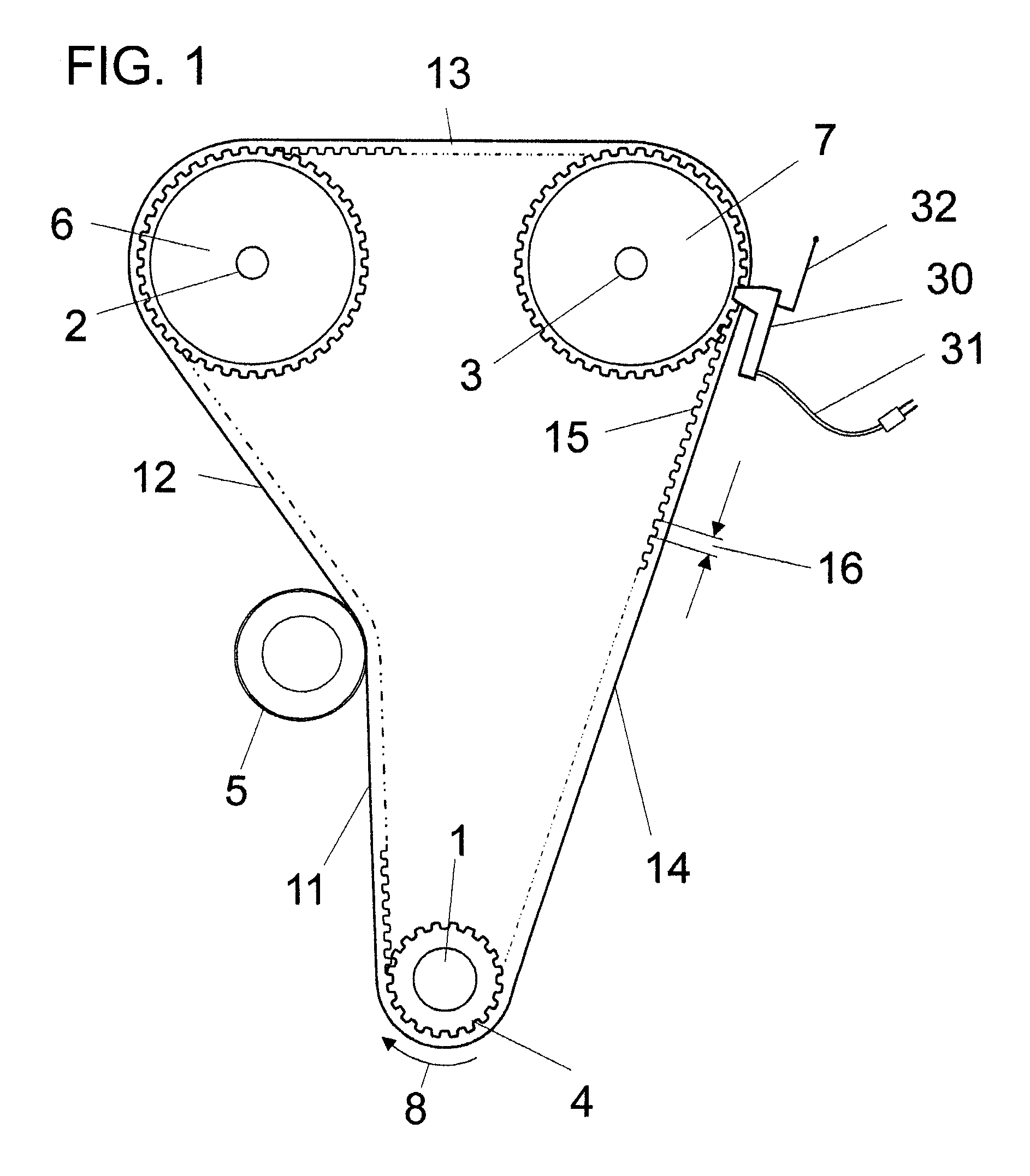
[0013]FIG. 1 shows an elevational view of a belt drive with a suitable position of the sensing device;

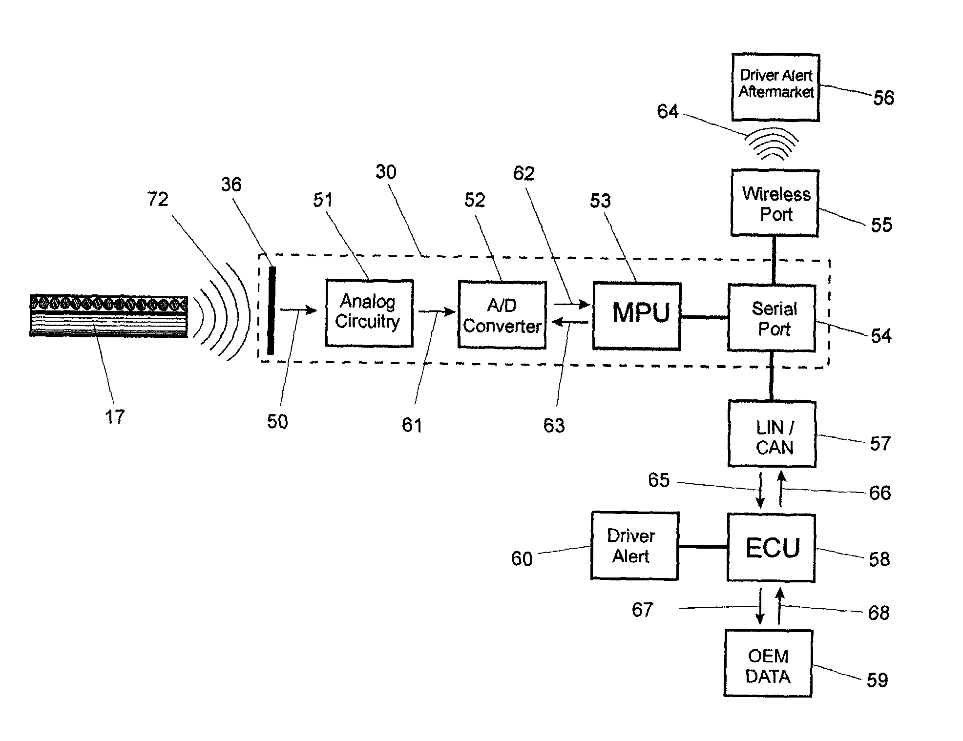
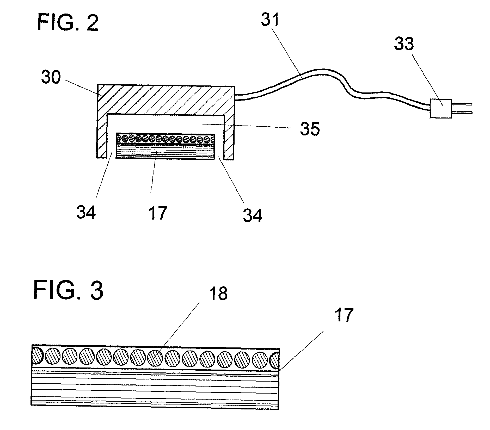
[0014]FIG. 2 shows a sectional view of the sensing device and adjacent belt structure;

[0015]FIG. 3 shows a sectional view of a typical belt structure;

[0016]FIG. 4 shows a side view of a typical belt structure;

[0017]FIG. 5 shows an elevational view of a belt depicting a failure mode when a typical belt is showing exposed fiber cord and typical structural deficiencies;

[0018]FIG. 6 shows the side view of a belt depicting the failure of an individual belt tooth structure;

[0019]FIG. 7 shows an elevational view of a belt drive depicting the typical modes of vibration in the belt span between two components;

[0020]FIG. 8 shows a sectional view of a typical belt structure depicting the preferred perpendicular pl...


PUM


Abstract

An apparatus and method to monitor endless belts and related belt drive systems by non-contact sensors for wear or an anomalous function, determining the state of belt drive system and detecting early stages of belt and system failure. A sensing unit featuring one or several independent sensor elements is placed near a belt of a polymer matrix with a fiber cord load bearing core to monitor several simultaneously occurring normal modes of operation. The sensor can determine soundness of the whole timing drive continuously by processing the collected signal and detecting structural damage. The collected data is processed by a microcontroller integrated with the sensor. The apparatus and method uses a non-contacting capacitor array having sensing element(s) connected to electronic circuitry that is adapted to sense the dynamic capacitance change coupled with electrocapacitive and piezoelectric effects exhibited by the belt. The sensor continuously monitors the belt during normal operation.

Description

BACKGROUND OF THE INVENTION[0001]In the field of power transmission, belt drives are the preferred means to couple rotational elements. They are traditionally divided into two general categories: non-synchronous and synchronous belt drives. In vehicles, both categories are used extensively. Non-synchronous drives are the preferred means to drive accessories such as water pumps, air-conditioning compressors, power steering pumps and alternator units. Synchronous drives, commonly referred to as timing drives, have been the preferable means to drive overhead camshaft systems and are widely used in internal combustion engines wherever synchronicity of a driven component is necessary. An example of such a drive is shown in FIG. 1.[0002]Timing belts are typically a composite of fiberglass, woven fabrics, rubber and other various polymers. All these materials exhibit piezoelectric properties: they are capable of generating electrical charges while they are being deformed. Under normal oper...

Claims


Application Information

Patent Timeline
IPC IPC(8): G08B21/00G01M13/023G01D5/12G01R29/22
CPCB65G43/02F16G1/28G01N27/24F16H57/01G01M13/023F16H7/02B65G43/00G01M13/02G01M17/00
Inventor LIPOWSKI, MATS
Owner LIPOWSKI MATS
Why Eureka
Try Eureka