
Method for determining an electrical variable

a technology of electrical variables and voltages, applied in the direction of impedence measurements, instruments, transportation and packaging, etc., can solve the problems of insufficient measurement of the voltage of the vehicle electrical system alone to predict the performance of the electrical power supply, and the failure of all functions of the assembly to be maintained

Active Publication Date: 2022-11-15
ROBERT BOSCH GMBH
View PDF4 Cites 0 Cited by
  • Summary
  • Abstract
  • Description
  • Claims
  • Application Information

AI Technical Summary

Benefits of technology

The patent text describes a method for improving the accuracy of determining electrical variables in a vehicle electrical system, by minimizing the impact of sensor measuring errors. This can lead to better diagnosis quality of the system and allow for decentralized monitoring of parts of the system. The technical effect of this method is improved accuracy and efficiency in monitoring and diagnosing vehicle electrical systems.

Problems solved by technology

If, due to the voltage drop across at least parts of the supply line, an excessively low voltage is applied at the connection terminals of such assemblies, it is possible that all functions of the assemblies may no longer be maintained if such a voltage drop sinks below a shutdown threshold of the assembly.
Otherwise, a resulting performance of the assemblies may be restricted due to the lower voltage.
The measurement of the voltage of the vehicle electrical system alone is not sufficient to predict the performance of the electrical power supply, in particular due to resistances in a supply line, since the maximum power is seldom demanded during normal operation.
In branched vehicle electrical systems, it is often not possible to detect errors due to an absence of measuring points or sensors, in particular because there are no values of external currents, which are not measured.

Method used


Image

  • Method for determining an electrical variable
  • Method for determining an electrical variable

Examples


Embodiment Construction

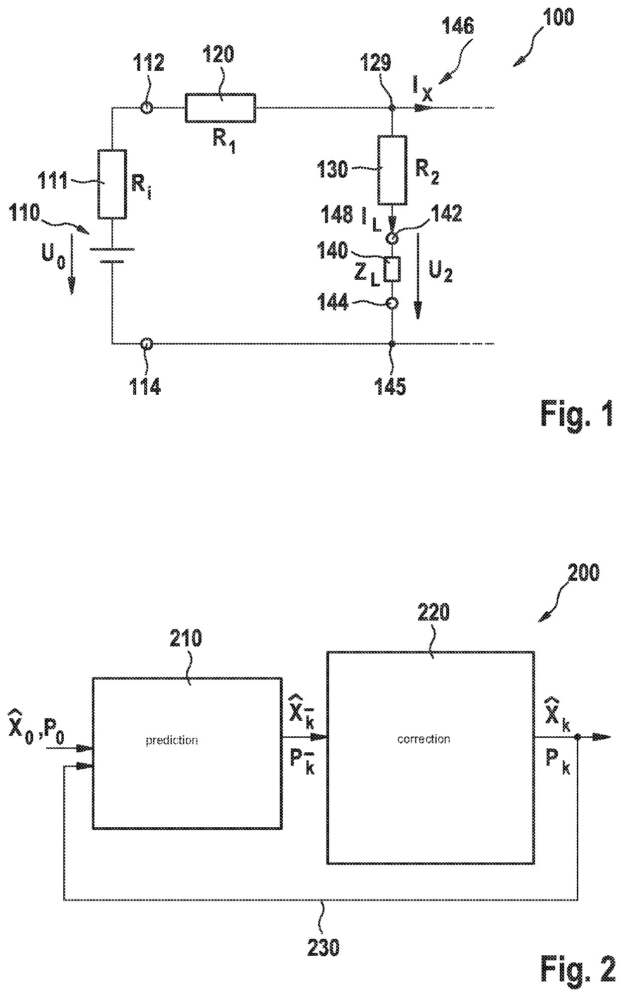
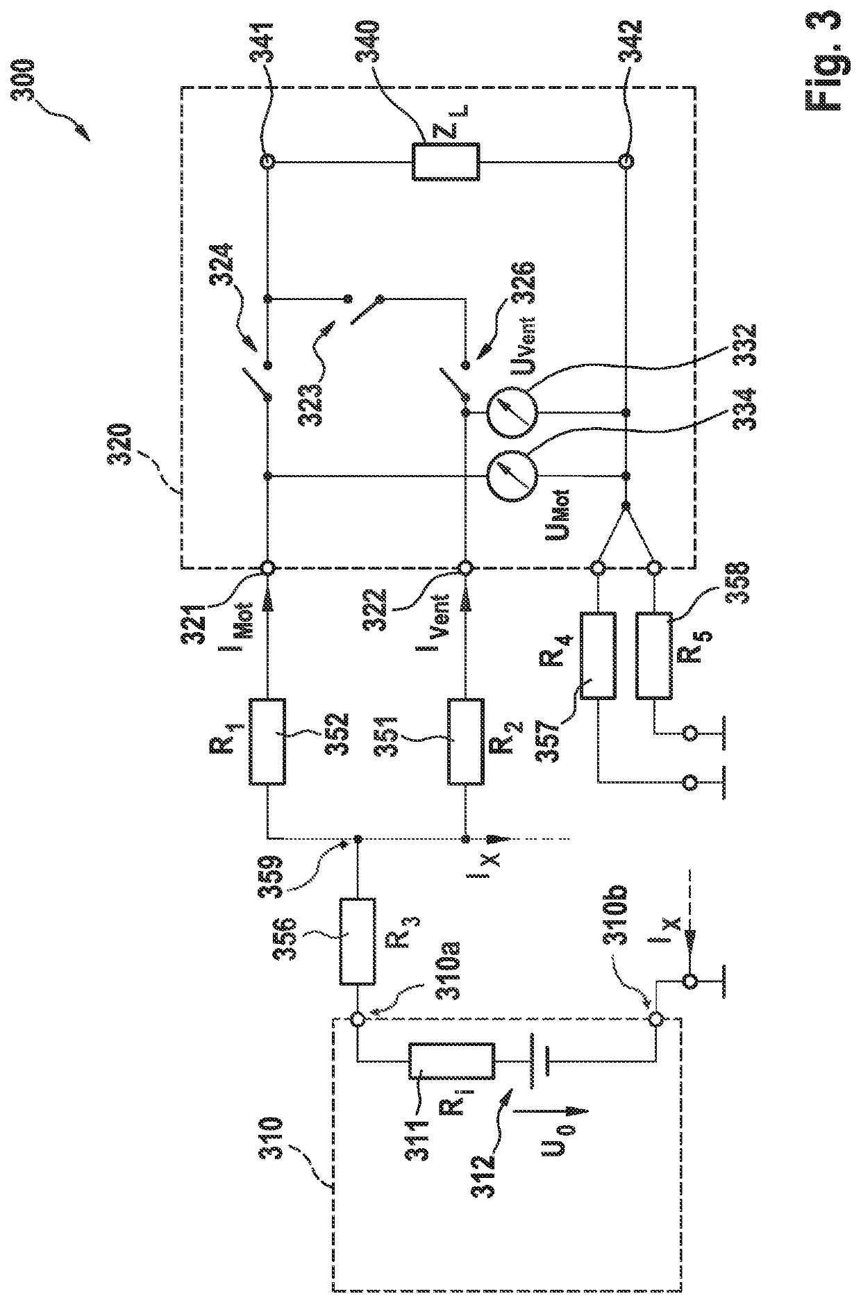
[0070]The method for determining an electrical variable of at least one component of a part of the vehicle electrical system is described with reference to FIGS. 1, 2, and 3.

[0071]FIG. 1 outlines a part of a vehicle electrical system 100, using which a control unit 140 of an intelligent brake (IB) is supplied with electrical power at its terminals 142, 144. Power source 110, which has a source voltage U0, including its internal resistance 111 connected in series, is directly electrically connected at a first output terminal 114 to second terminal 144 of control unit 140. Second output terminal 112 of power source 110 is connected via a first supply line resistivity 120 at a neutral point 129 including a second supply line resistivity 130 to first terminal 142 of control unit 140. Control unit 140 represents the impedance unit. The power source may be designed in the form of an energy accumulator, for example a battery.

[0072]The value of supply resistance 120 includes all resistors w...


PUM


Abstract

A method for determining an electrical variable of a component of part of a vehicle electrical system including at least one external current and an electrical impedance unit. A measuring unit is configured to generate a plurality of current and voltage values for each of at least two different operating points of the impedance unit. The method includes: providing the current values of the impedance unit at a first operating point and at least one second operating point; providing the voltage values of the impedance unit at a first operating point and at least one second operating point; corresponding current and voltage values being associated with one another; determining the at least one electrical variable of the component based on a parameter estimation method and an electrical model of the part of the vehicle electrical system and at least part of the corresponding current and voltage values.

Description

CROSS REFERENCE[0001]The present application claims the benefit under 35 U.S.C. § 119 of German Patent Application No. DE 102019219840.6 filed on Dec. 17, 2019, which is expressly incorporated herein by reference in its entirety.FIELD[0002]The present invention relates to a method for determining an electrical variable of at least one component of a part of a vehicle electrical system, the part of the vehicle electrical system including at least one external current.BACKGROUND INFORMATION[0003]In modern vehicles, essential functions, for example, the steering, the braking system, or the surroundings detection, are dependent on a reliable vehicle electrical system supply. This applies in particular to at least semi-automated mobile platforms. It is indispensable to monitor the electrical supply of safety-relevant consumers and ensure that in the event of a system failure, the mechanical fallback level is not possibly available to the driver to avoid an emergency situation.[0004]Again...

Claims


Application Information

Patent Timeline
Patent Type & Authority Patents(United States)
IPC IPC(8): G01R27/16B60R16/03
CPCG01R27/16B60R16/03G01R31/00G01R27/02
Inventor SUELZLE, HELMUTMOTZ, JUERGENLUECKEL, PATRICKLE, QUANG-MINH
Owner ROBERT BOSCH GMBH
Learn More