Semi-rigid collapsible container

a container and semi-rigid technology, applied in the field of polypropylene containers, can solve the problems of limited vertically disposed flex panels, failure under any increased load, and inability to meet the vacuum pressure of containers, and achieve the effect of efficient compensating for vacuum pressure in containers

Inactive Publication Date: 2006-07-18
CO2 PAC
View PDF19 Cites 104 Cited by
  • Summary
  • Abstract
  • Description
  • Claims
  • Application Information

AI Technical Summary

Benefits of technology

[0012]Preferably the vacuum panel is adapted to fold inwardly under an externally applied mechanical force in order to completely remove vacuum pressure generated by the cooling of the liquid contents, and to prevent expansion from the collapsed state when the container is uncapped.

Problems solved by technology

The amount of ‘flex’ available in prior art, vertically disposed flex panels is limited, however, and as the limit is reached the force is transferred to the side-wall, and in particular the areas between the panels, of the container causing them to fail under any increased load.
The more force that is exerted results in a demand for increased container wall-thickness, which in turn results in increased container cost.
The principal mode of failure in all prior art known to the applicant is non-recoverable buckling, due to weakness in the structural geometry of the container, when the weight of the container is lowered for commercial advantage.
Such accordion-like structures are inherently unsuitable for hot-fill applications, as they exhibit difficulty in maintaining container stability under compressive load.
Further, labels cannot be properly applied over such sections due to the vertical movement that takes place.
This results in severe label distortion.

Method used


Image

  • Semi-rigid collapsible container
  • Semi-rigid collapsible container
  • Semi-rigid collapsible container

Examples


Embodiment Construction

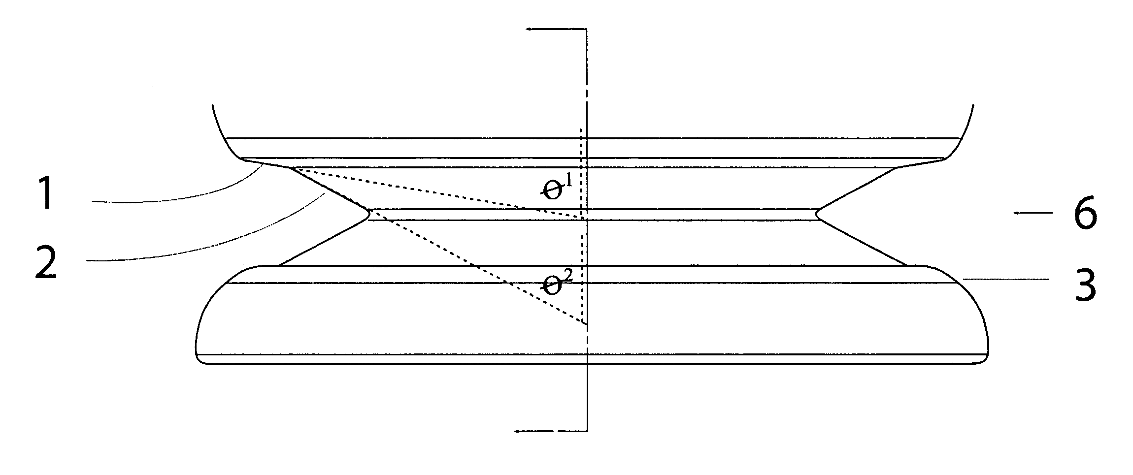
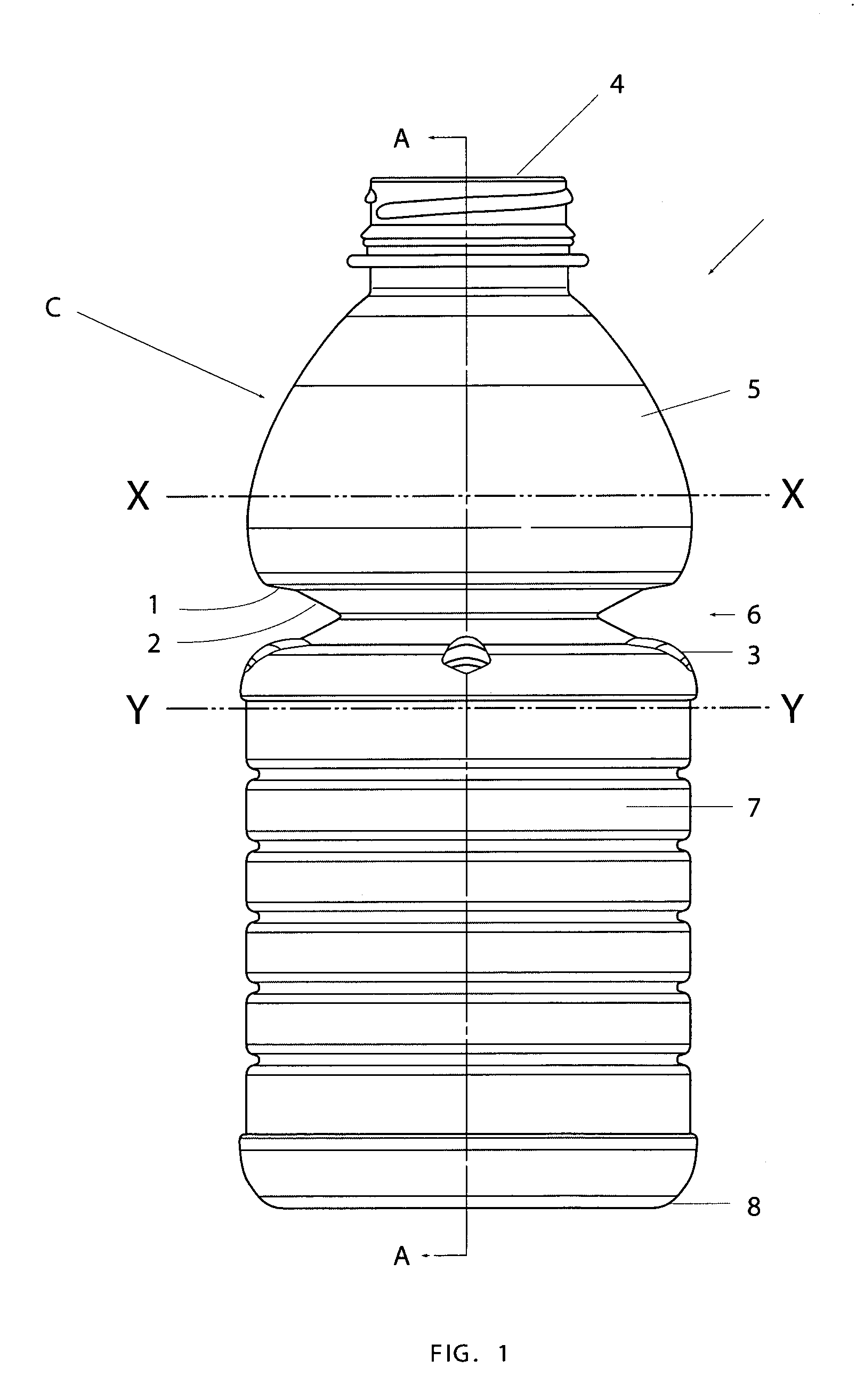
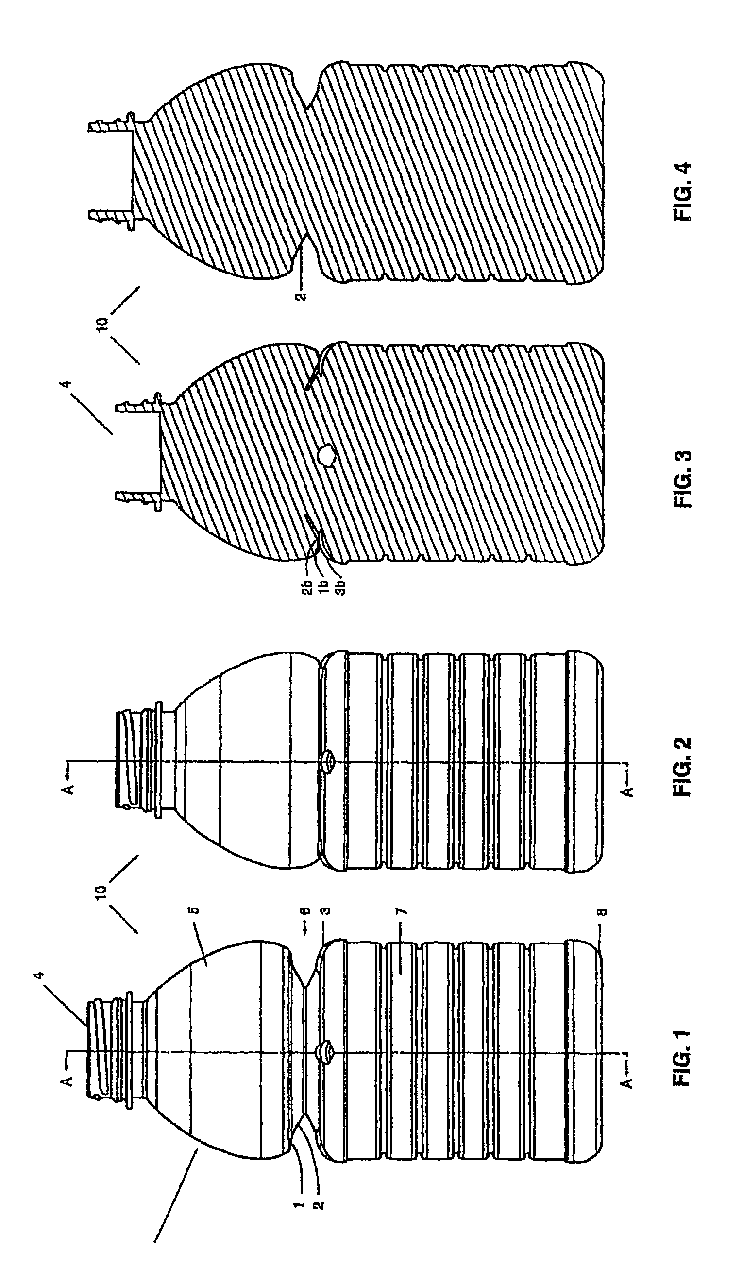
[0026]The present invention relates to collapsible semi-rigid containers having a side-wall with at least one substantially vertically folding vacuum panel section which compensates for vacuum pressure within the container.

[0027]Preferably in one embodiment the flexing may be inwardly, from an applied mechanical force. By calculating the amount of volume reduction that is required to negate the effects of vacuum pressure that would normally occur when the hot liquid cools inside the container, a vertically folding portion can be configured to allow completely for this volume reduction within itself. By mechanically folding the portion down after hot filling, there is complete removal of any vacuum force generated inside the container during liquid cooling. As there is no resulting vacuum pressure remaining inside the cooled container, there is little or no force generated against the sidewall, causing less stress to be applied to the container sidewalls than in prior art.

[0028]Furth...


PUM

PropertyMeasurementUnit
mechanical forceaaaaaaaaaa
internal pressureaaaaaaaaaa
pressureaaaaaaaaaa

Abstract

A semi-rigid collapsible container (10) has a side-wall with an upper portion (5), a central portion (6), a lower portion (7) and a base (8). The central protion (6) includes a vacuum panel portion having a control portion (2) and an initiator portion (1). The control portion (2) is inclined more steeply in a vertical direction, i.e. has a more acute angle relative to the longitudinal axis of the container (10), than the initiator portion (1). On low vacuum force being present within the container panel following the cooling of a hot liquid in the container (10), the initiator portion (1) will flex inwardly to cause the control protion (2) to invert and flex further inwardly into the container (10) and the central portion (6) to collapse. In the collapsed state upper and lower portions of the central portion (6) may be in substantial contact so as to contain the top-loading capacity of the container (10). Raised ribs (3) made an aditional support for the container in its collapsed state. In another embodiment the telescoping of the container back to its original position occurs when the vacuum force is released following removal of the container cap.

Description

RELATED APPLICATIONS[0001]This application is related to New Zealand Patent Application entitled, Semi-Rigid Collapsible Container, filed on Aug. 31, 2000, Application No. 506684; and New Zealand Patent Application entitled, Semi-Rigid Collapsible Container, filed on Jun. 15, 2001, Application No. 512423, which are fully incorporated herein by reference and claims priority therefrom.BACKGROUND TO INVENTION[0002]This invention relates to polyester containers, particularly semi-rigid collapsible containers capable of being filled with hot liquid, and more particularly to an improved construction for initiating collapse in such containers.[0003]‘Hot-Fill’ applications impose significant mechanical stress on a container structure. The thin side-wall construction of a conventional container deforms or collapses as the internal container pressure falls following capping because of the subsequent cooling of the liquid contents. Various methods have been devised to sustain such internal pre...

Claims


Application Information

Patent Timeline
Patent Type & Authority Patents(United States)
IPC IPC(8): B65D6/08B65D6/10B65DB65D1/02B65D8/14B65D79/00
CPCB65D1/0223B65D79/005Y10S215/90B65D2501/0036B65D1/0207B65D79/0084B65D1/44B67C3/045B65B61/24B65B7/2835B65B3/04B65B7/28B65D21/086
Inventor MELROSE, DAVID MURRAY
Owner CO2 PAC
Why Eureka
Try Eureka