Sutureless occular surgical methods and instruments for use in such methods

a surgical method and sutureless technology, applied in the field of sutureless surgical methods and instruments, can solve the problems of large incisions that are not easy to self-seal, and achieve the effect of minimizing damage to the retina

Inactive Publication Date: 2006-07-18
THE JOHN HOPKINS UNIV SCHOOL OF MEDICINE
View PDF24 Cites 114 Cited by
  • Summary
  • Abstract
  • Description
  • Claims
  • Application Information

AI Technical Summary

Problems solved by technology

Because the incisions through the sclera are large enough to pass 19 or 20 gauge instruments, the incisions are typically too large to self-seal.

Method used


Image

  • Sutureless occular surgical methods and instruments for use in such methods
  • Sutureless occular surgical methods and instruments for use in such methods
  • Sutureless occular surgical methods and instruments for use in such methods

Examples


second embodiment

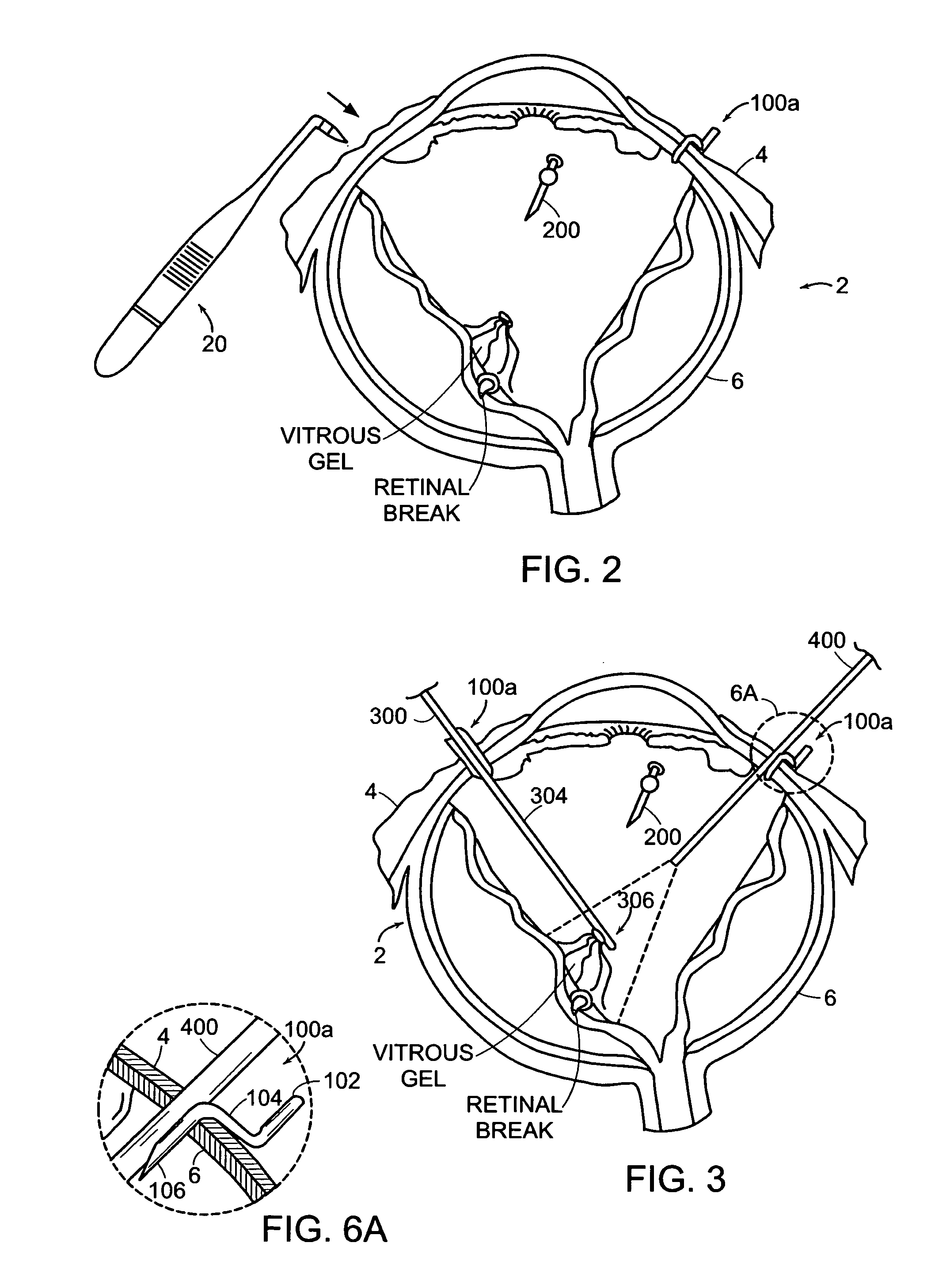
[0068]Now referring to FIG. 8 there is shown an entry alignment device 100b according to the present invention that includes an insertion member 110 and a stop member 112 that is affixed about the exterior of the insertion member 110. The entry alignment device 100b of this embodiment is configured and arranged so that in use, the portion of the insertion member 110 that is below the stop member 112 is passed through each of the conjunctiva 4 and the sclera 6. Additionally, in use the entry alignment member 100b is inserted until the stop member 112 is proximal the exterior surface of the eye 2 similar to that shown for the stop portion 104 in FIG. 6A.

[0069]In the illustrated embodiment, an end of the insertion member 110 is securably received in the stop member 112. Alternatively, the entry alignment device is constructed such that the insertion and stop members 110,112 form an integral structure. In yet another embodiment, the insertion member 110 and stop member 112 are configure...

third embodiment

[0075]Now referring to FIG. 9 there is shown an entry alignment device 100c in the shape of a conventional cannula, that includes an insertion member 120 and a stop member 122 that is affixed to the insertion member. In a particular embodiment, the insertion member and the stop member form an integral, one-piece structure. The entry alignment device 100c of this embodiment is configured and arranged so that in use the portion of the insertion member 120 that is below the stop member 122 is passed through each of the conjunctiva 4 and the sclera 6. Additionally, in use the entry alignment member 100b is inserted until the stop member 122 is proximal the exterior surface of the eye 2 similar to that shown for the stop portion 104 in FIG. 6A.

[0076]In the illustrated embodiment, the insertion member 120 is a tubular member having a lumen 124 extending between the ends of the insertion member and the stop member 122 includes therein a through aperture 126 that communicates with the inse...

fourth embodiment

[0082]Now referring to FIGS. 10A,B there is shown entry alignment devices 100d,e according to the present invention that are formed by shaping a solid or hollow cylindrical member, for example a metal wire, into a predetermined shape or configuration. In FIG. 10A there is shown an entry alignment device 100d including an arcuate portion 130 from which extends two leg portions 132 that are spaced from each other and generally parallel to each other. Each leg portion includes an upper segment 134 and a lower segment 136, where the lower segment is at an angle with respect to the upper segment so that the upper segment.

[0083]The lower segments 136 are sized so that each extends through the conjunctiva 4 and sclera 6 when disposed in the entry aperture. The angle between the upper segments 134 and the lower segments 136 is established and the upper segments are sized so that the upper segments act as a stop, to limit the amount of insertion as well as to restrain the entry alignment dev...


PUM


Abstract

Featured are new methods for performing intra-ocular surgery that allow surgical personnel to access the intra-ocular volume to perform a surgical procedure or technique but which does not require the use of sutures to seal the sclera and / or conjunctiva following the procedure. The methods of the present invention generally include providing an entry alignment device and inserting the entry alignment device into an eye through both the conjunctiva and sclera so as to form an entry aperture that extends between the exterior of the eye and the intra-ocular volume within the eye. The provided alignment device is configured so as to form or provide an aperture or opening in each of the conjunctiva and sclera of the eye and to maintain these apertures or openings in each of the conjunctiva and sclera aligned during the surgical procedure so these apertures or openings form the entry aperture. In more particular aspects, the provided entry alignment device is sized such that when the entry alignment device is removed from the eye following the completion of the surgical procedure, the aperture or opening formed in the sclera seals without the use of sutures. In a more specific aspect of the present invention, the provided entry alignment device is sized such that the apertures or openings and thus the entry aperture are self sealing. In other embodiments, a plurality of entry alignment devices are provided so a plurality of entry apertures can be formed in the eye. The invention also features a high speed vitreous cutting and aspirating device particularly configured for use in such methods and surgical procedures and techniques as well as the related entry alignment devices and other surgical instruments.

Description

FIELD OF INVENTION[0001]The present invention relates to methods for performing surgery and instruments used therewith, in particular sutureless surgical methods and techniques and the instrumentalities therefor which do not involve the use of sutures to seal the openings through which the instrumentalities are inserted, and more particularly, to surgical methods involving the eye (e.g., retinal tear or detachment surgery, macular hole surgery) as well as the instruments or devices used during such surgical procedures, where the openings in the eye provided for the use of the instruments need not be sealed by suturing.BACKGROUND OF THE INVENTION[0002]Retinal tears can occur when the vitreous, a clear gel-like substance that fills the center of the eye, pulls away from the retina thereby leaving behind a tear or hole in the retina. Rhegmatogenous retinal detachments can result if the retinal breaks (i.e., tears or holes in the retina) are not treated. With retinal breaks, fluid from ...

Claims


Application Information

Patent Timeline
Patent Type & Authority Patents(United States)
IPC IPC(8): A61F11/00A61F9/007
CPCA61F9/00727A61F9/007
Inventor DE JUAN, JR., EUGENESHELLEY, TERRY H.BARNES, AARON C.JENSEN, PATRICK S.
Owner THE JOHN HOPKINS UNIV SCHOOL OF MEDICINE
Why Eureka
Try Eureka