
Data processing apparatus and method for d=2 optical channels

a data processing apparatus and optical channel technology, applied in the field of data processing apparatus, can solve the problems of poorer performance on shorter target responses, severe degradation of detection performance, and loss of bit-error-rate performance, so as to improve detection reliability, enhance detection capability, and improve detection reliability

Inactive Publication Date: 2006-07-18
DATA STORAGE INST
View PDF14 Cites 8 Cited by
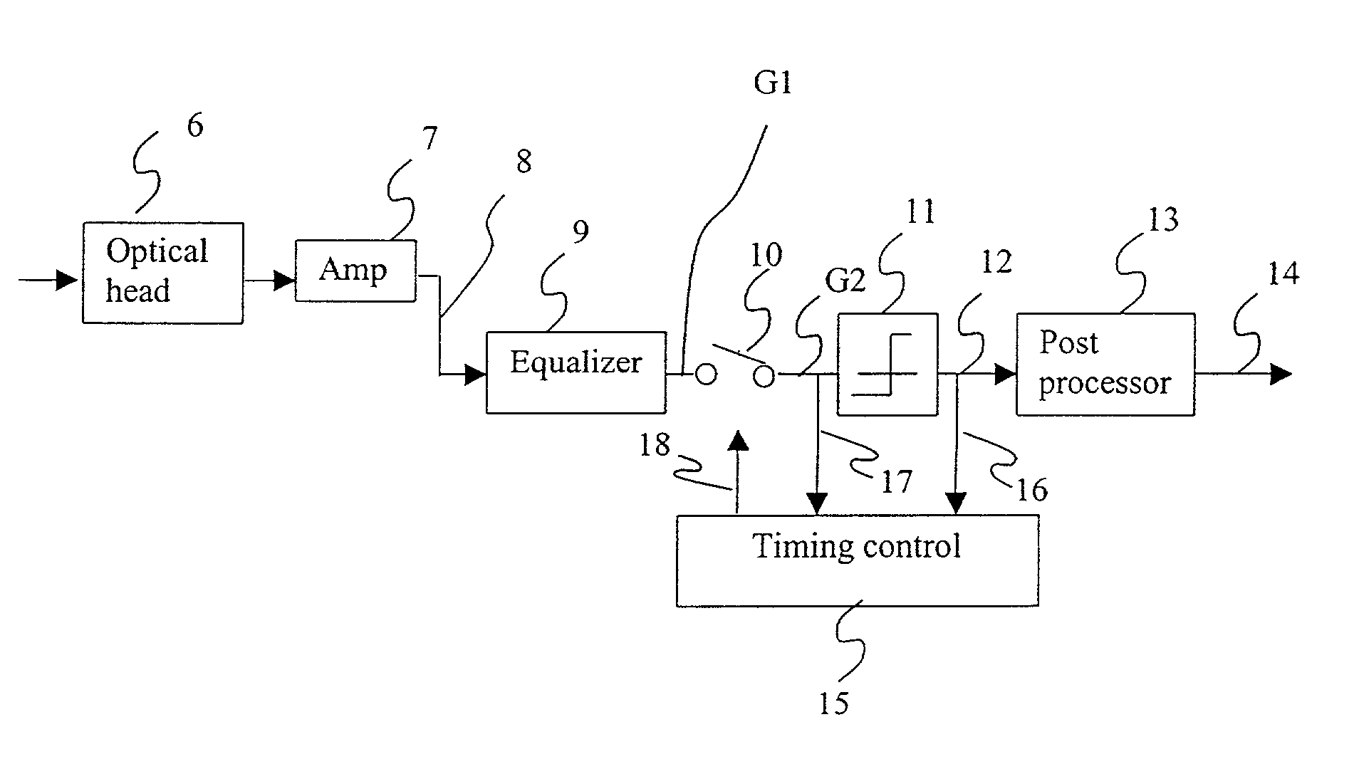
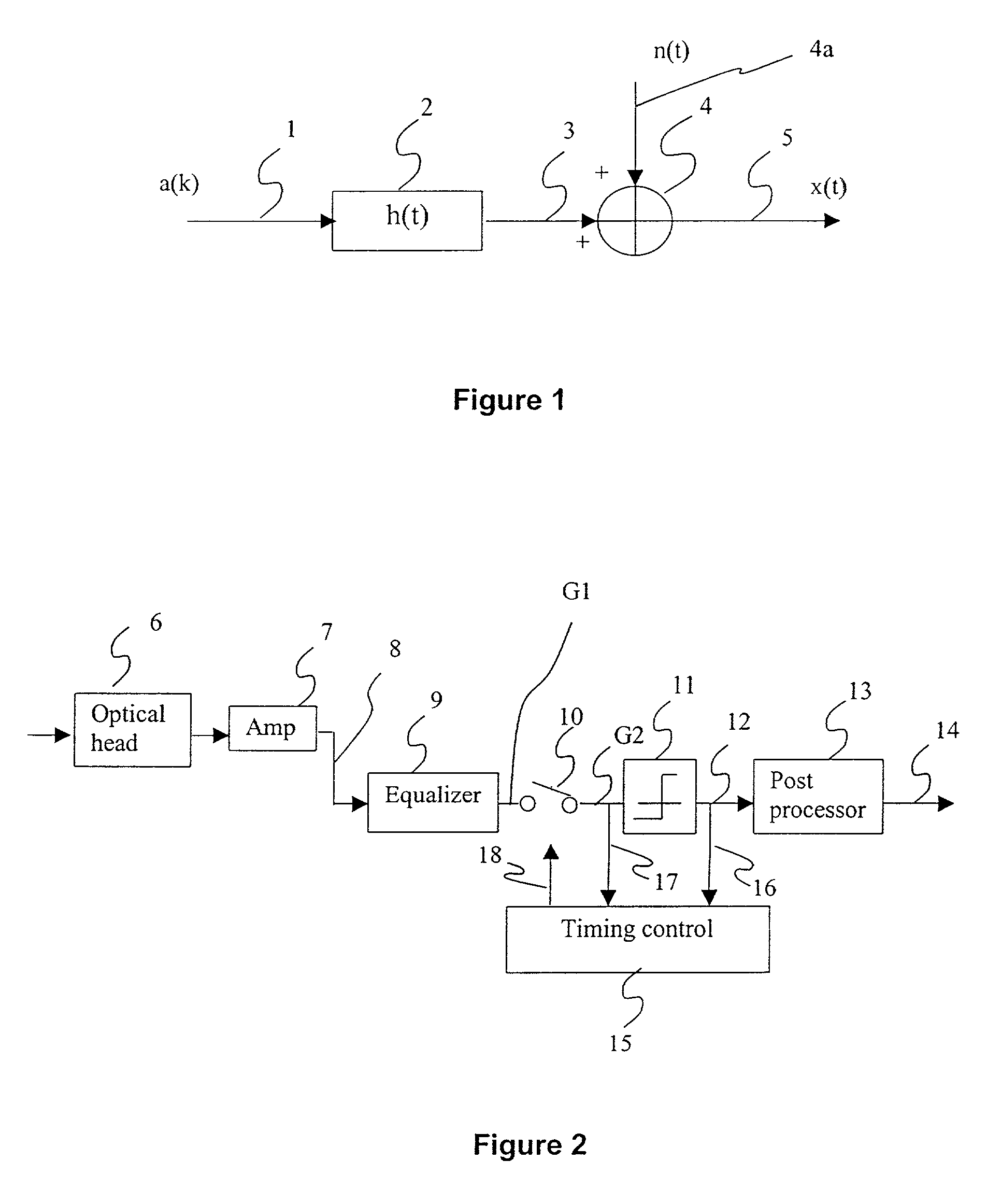
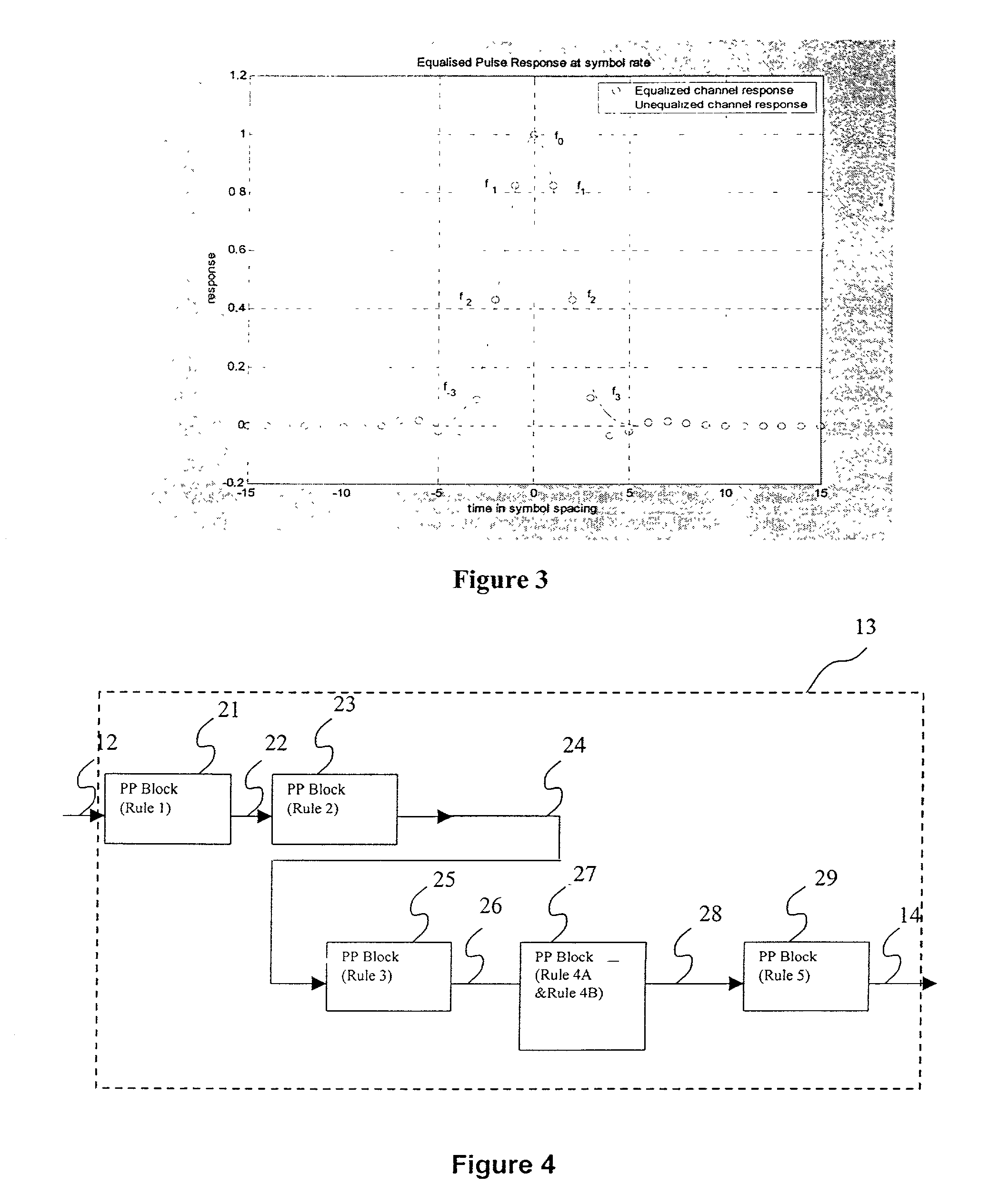
  • Summary
  • Abstract
  • Description
  • Claims
  • Application Information

AI Technical Summary

Benefits of technology

[0004]It is an object of the present invention also to provide a data processing apparatus and method which is reliable for detection and has enhanced detection capability and which is capable of achieving performance close to the maximum likelihood lower bound (MLB) over a range of channel densities.
[0006]Further, a procedure to design the equalizer to have symmetric partial response target of known length and optimum shape, which is unknown apriori, is provided. The resultant target response is also used in post-processing blocks. The post-processor comprises five sub-blocks. The first two blocks are advantageously designed to detect and correct the d=2 code constraint violations, while the other three blocks are designed to increase the reliability of detection of certain data bits which cause the first three dominant error events to occur at the output. The reliability is achieved through minimum energy criterion from the two possible streams of possible outputs. Simulations results are also included hereinafter to show the superior performance of the simple post-processing detector of the invention over a reference 5-tap target partial response Viterbi detector.
[0007]Thus, according to one aspect of the present invention there is provided a data processing apparatus comprising: means for generating a signal representative of recorded data on a data storage medium; filtering means for receiving the generated signal and equalising the generated signal response at a predetermined level; and signal correcting means for detecting a plurality of multiple-bit data representative of the equalised signal and processing said multiple-bit data in dependence upon a predetermined set of data correction rules which, in operation of the apparatus, has the effect of enhancing the detection capability of the apparatus.
[0008]According to another aspect of the present invention there is provided a data processing system incorporating means for detecting multiple-bit data representative of an equalised signal and means for processing said data in dependence upon a predetermined set of data correction rules such as to enhance the detection capability of the system.
[0009]The present invention also extends to a method of enhancing the detection capability of the aforementioned data processing apparatus comprising generating a signal representative of recorded data on a data storage medium; equalising the generated signal response at a predetermined level, and detecting a plurality of multiple-bit data representative of the equalised signal and processing said multiple-bit data in dependence upon a predetermined set of data correction rules.

Problems solved by technology

ck. As the information storage density increases, the detection performance severely degrades due to inter-symbol interfere
roposed. Although these detectors are simple, their bit-error-rate performance is away from maximum achievable per
ction systems. These give poorer performance on shorter target responses due to noise enhancement and for longer target responses, the detectors are enor

Method used


Image

  • Data processing apparatus and method for d=2 optical channels
  • Data processing apparatus and method for d=2 optical channels
  • Data processing apparatus and method for d=2 optical channels

Examples


Embodiment Construction

[0027]First, the procedure to design the equalizer is described, and thereafter, the design of post-processing blocks is described. The equalized response is further used in post-processing blocks.

[0028]In a conventional optical playback system, a focused beam scans a recorded data pattern, which is in the form of pits (mark) and lands of varying length on the optical disk. The data pattern modulates intensity profile of the reflected light beam. Signal changes from a low-to-high (or high-to-low) at the edges of pits and remains high (or low) in between. These changes in the signal for a symbol on the DVD channel is modeled as Gaussian distributed light intensity profile convolved with a rectangular pulse of duration T, where T is the channel symbol period. Referring first to FIG. 1, which shows the conventional optical signal model in schematic form, the response of the channel to a transition at the leading mark edge is represented by g(t), and the symbol response is represented a...


PUM

PropertyMeasurementUnit
polaritiesaaaaaaaaaa
information storage densityaaaaaaaaaa
densitiesaaaaaaaaaa

Abstract

A data processing apparatus having a partial response forward equalizer (filter) with sufficient number of taps to result in 7-tap target response, designed by jointly optimizing the target response and the target coefficients to maximize an appropriate signal-to-noise ratio (SNR) at the detector input, followed by a new post-processing scheme enhances performance of the threshold based bit-by-bit detector designed for the d=2 optical channels. The resulting performance of the proposed scheme over a range of channel densities of 4.5 and below (used on EFM / EFMPlus coded channels for CD / DVD), is close to maximum-likelihood bound (MLB), and it is better than that of other schemes at channel densities of 4.5 and higher. Advantageously, the detector of the invention is simple in structure compared to conventional partial response Viterbi detector schemes. By processing the detected data in accordance with a set of data correction rules, the invention provides advantageous enhanced detection capacity.

Description

FIELD OF THE INVENTION[0001]The present invention relates to the design of a data processing apparatus for reproducing bits of information stored on a disk. More particularly, though not exclusively, the present invention concerns an improved data processing apparatus for optically reproducing bits of information stored on an optical disk.BACKGROUND OF THE INVENTION[0002]Detection systems, in general, have an equalizer followed by a detector. The equalizer shapes input signal from an optical disk read mechanism to have particular characteristics and the detector processes the equalized signal to retrieve the information stored on the optical disk. Peak detectors, threshold based bit-by-bit detectors with and without simple post-processing for d=2 code constraint violation, and partial response Viterbi detectors are the proposed (or used) detection schemes for DVD channels. Peak detection systems (see prior arts and systems described in U.S. Pat. No. 5,680,380 M. Taguchi et. al, U.S....

Claims


Application Information

Patent Timeline
Patent Type & Authority Patents(United States)
IPC IPC(8): G11B20/10G11C29/00G11B7/005G11B20/18H03M13/39H03M13/41
CPCH03M13/6343H03M13/39H03M13/41H03M13/6331G11B7/005G11B20/10009G11B20/10046G11B20/10055G11B2020/1461
Inventor INDUKUMAR, KALAHASTHI CHENCHUBI, LEI
Owner DATA STORAGE INST
Learn More